Overview:
Abstract The dual-channel driver UCC27201 with floating function is often used in isolated DC/DC power supplies. Practical applications have found that in some scenarios, the HO pin generates a false pulse at power-on. This false pulse causes the system to run the risk of abnormal startup. In this paper, the mechanism of false pulse generation is introduced in detail through actual simulation and circuit principle analysis. Two solutions for the error pulse are then provided and explained in detail.
1. Isolated power system design An isolated power system completes the DC/DC conversion, using a full-bridge topology with an output voltage of 12V. Among them, the original side driver of the whole bridge uses UCC27201, a total of two.
1.1 Isolated Power System Brief
The isolated power system performs a wide range of input voltage (36V~72V) to 12V conversion with an output power of 350W. The system uses a hard-switched full-bridge topology (HSFB) with synchronous rectification. Figure 1 shows a block diagram of the system, including the master chip LM5035, the driver UCC27201 placed on the primary side, the driver UCC27324 on the secondary side, and the isolator. 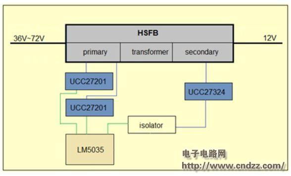
Figure 1: Block Diagram of Isolated Power System
1.2 Application of UCC27201
The UCC27201 is a MOSFET driver with floating function. It has two channels of high-side output and low-side output. It can be applied to topologies such as BUCK, half-bridge and full-bridge. The chip pins are described as follows:
â— VDD (Pin1): power supply pin, the range is 8V~17V, and the typical value is 12V.
â— VSS (Pin7): chip ground pin;
â— HI, LI (Pin5, Pin6): high-end drive input and low-end drive input;
â— HO, LO (Pin3, Pin8): high-end drive output and low-end drive output;
â— HB, HS (pin2, pin4): floating power supply and floating pin for high-end drive power supply;
As shown in Figure 2, in this power system, the two outputs of one UCC27201 drive the two MOSFETs on the same side of the full bridge, and the main connection network is labeled as blue font. The other output of the other UCC27201 is the other side of the bridge that drives the full bridge. 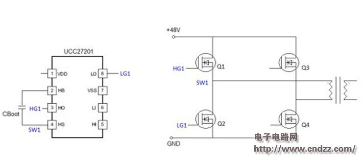
Figure 2: Practical application of the driver UCC27201 The actual drive signal using the above application circuit is shown in Figure 3. It includes two stages: soft start and normal operation.
During the soft-start phase, the duty cycle of the drive signal for the MOSFET labeled Q1 is much less than 50%, while the duty cycle for the drive signal for Q2 is more than 50%, which is complementary to the duty cycle of the drive signal for Q1. The relationship between the Q3 and Q4 drive signals is the same as above.
(Please read the PDF for details)
The WIFI hotspot, including the internal data processing and transmission of the CPE, is divided into two completely independent channels. The internal network channel carries WIFI, is managed by the user, and is authenticated by the account password. The external network channel is controlled and controlled by the operator. Two-way authentication, remote monitoring, encrypted transmission, dynamic passwords, strict isolation measures on software and some hardware, to achieve carrier-class security standards, to achieve complete isolation from inside and outside WIFI, external network channels authenticate users through SIM cards, all of the operators Users can access the CPE through the external network to access the 4G / 5G network through the CPE to achieve carrier-class security and achieve standby Internet calls through the external network channel, which is no different from accessing the network through the operator`s base station.
4G CPE Router,Install Wireless Sim Card 4G,4G Router Wifi Modem,CPE Install Wireless Sim Card 4G
Shenhzhen Tongheng Weichuang Technology Co., Ltd , https://www.thwclte.com