Generally speaking, the principle of adding constraints is to first add global constraints, then add local constraints, and the local constraints are loose. The goal is to relax constraints as much as possible, increase the probability of successful routing, and reduce ISE placement and routing time. Typical global constraints include periodic constraints and offset constraints. When adding global timing constraints, you need to divide different clock domains according to the clock frequency, add their own period constraints; then add offset constraints to the input and output port signals to add additional constraints to the on-chip logic.
1. Periodic constraintThe periodic constraint is a basic timing constraint attached to the clock network to ensure that the timing of all synchronization components in the clock region meets the requirements. When analyzing timing, the period constraint can automatically handle the inversion problem of the register clock end. If the adjacent sync element clocks have opposite phases, the delay will be automatically limited to half of the period constraint value, which is equivalent to reducing the clock period constraint. The value, so in practice, generally do not use the rising and falling edges of the clock signal at the same time.
The highest frequency at which a hardware design circuit can operate depends on the inherent setup hold time inherent in the chip's internal components, as well as the logic and routing delay between the sync components. Therefore, the highest frequency of the circuit is determined by both the code and the chip. The same program can achieve a higher maximum operating frequency on a chip with a higher speed grade. Similarly, the speed-optimized code has higher work on the same chip. Frequency, in practice, often takes the balance between the two.
Before adding a clock cycle, you need to have a reasonable estimate of the expected clock period of the circuit, so that you do not attach too loose or too tight cycle constraints, too loose constraints can not meet the performance requirements, too tight constraints will increase the layout and routing The difficulty of achieving the results is not necessarily ideal. A common engineering strategy is that the duration of the additional clock cycle constraint is 90% of the expected value, ie the highest frequency of the constraint is about 110% of the actual operating frequency.
There are two ways to attach clock cycle constraints: one is a simple method, and the other is a recommended method. The easy way is to attach the period constraint directly to the register clock network line. The syntax is as follows:
[Constrained signal] PERIOD = { period length} {HIGH | LOW} [pulse duration]; where the content in [] is optional, the content in {} is mandatory, and the "|" indicates the selection. [Constrained signal] can be "Net net_name" or "TIMEGRP group_name", the former means that the period constraint acts on the synchronization component driven by the net, and the latter means constrains to the signal group defined by TIMEGRP (such as trigger, latch) And RAM, etc.). { Period length} is the required clock period. You can use ms, s, ns, and ps. The default value is ns, and the unit is not case sensitive. {HIGH | LOW} Used to specify whether the first pulse is high or low during the specified period. [Pulse Duration] Used to specify the duration of the first pulse. It can be selected in units of ms, s, ns, and ps. The default value is ns. If it is the default, the default is 50% duty cycle. As the statement:
Net " clk_100MHz" period = 10ns High 5ns;
The period of the signal clk_100MHz is specified as 10ns, and the high level is sustained for 5ns. This constraint will be added to the component driven by the signal clk_100MHz.
The recommended method is often used to constrain a clock network with complex derivation relationships. The basic syntax is:
TIMESPEC "TS_idenTIfier" = PERIOD "TNM_reference" {cycle length}
{HIGH | LOW} [pulse duration];
Among them, TIMESPEC is a basic timing-related constraint used to mark timing specifications. "TS_identifier" is represented by the keyword TS and the user-defined identifier, which together form a timing specification called TS attribute definition, which can be arbitrarily referenced in the constraint file, greatly enriching the definition of the derived clock. When using, first define the clock grouping, and then add the corresponding constraints, such as:
NET " clk_50MHz" = " syn_clk";
TIMESPECT "TS_syn_clk" = PERIOD "syn_clk" 20 HIGN 10;
TIMESPEC uses the identifier to define the syntax of the derived clock as:
TIMESPEC "TS_identifier2" = PERIOD "timegroup_name" "TS_identifier1"
[* | /] Multiple factor [+| -] phasevalue [unit]
Where TS_identifier2 is the clock to be derived, TS_identifier1 is the defined clock, "multiplier" is used to give the multiple of the period, and phasevalue gives the phase relationship between the two. Such as:
Define the system clock clk_syn :
TIMESPEC " clk_syn" = PERIOD " clk" 5ns;
The inverted clock clk_syn_180 and the divide-by-2 clock clk_syn_half are given below:
TIMESPEC " clk_syn_180" = PERIOD " clk_180" clk_syn PHASE + 2.5ns;
TIMESPEC " clk_syn_180" = PERIOD " clk_half " clk_syn / 2;
2. Offset constraintOffset constraints are also a class of basic timing constraints that specify the relative timing relationship between the external clock and the data input and output pins. They can only be used for port signals and cannot be applied to internal signals, including OFFSET_IN_BEFORE, OFFSET_IN_AFTER, OFFSET_OUT_BEFORE, OFFSET_OUT_AFTER, etc. 4 basic constraints. The basic syntax of an offset constraint is:
OFFSET = [IN | OUT] "offset_time" [units] {BEFORE | AFTER} " clk_name"
[TIMEGRP "group_name"];
Where [IN | OUT] indicates whether the input or output is constrained. “offset_time†is the time difference between the data and the valid clock edge. {BEFORE| AFTER} indicates whether the time difference is before or after the valid clock, “clk_name†is the name of the valid clock, and [TIMEGRP “group_nameâ€] is the group added by the user. The signal, by default, defaults to all triggers driven by the clock clk_name. The offset constraint informs the placer of the arrival time of the input data, so that the process of place and route can be accurately adjusted, so that the constraint signal establishment time meets the requirements.
1) "OFFSET IN" offset constraint
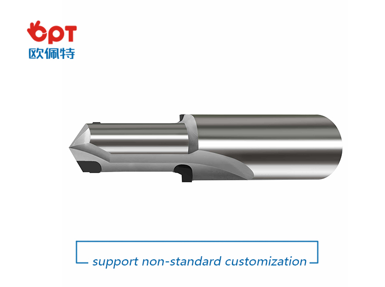
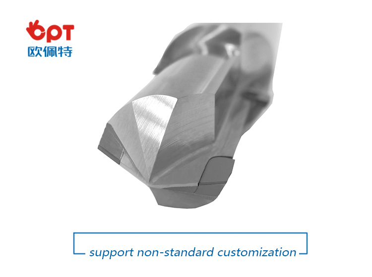
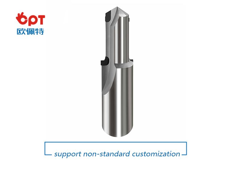
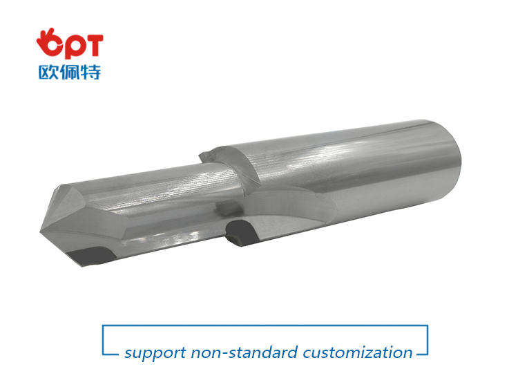
Other PCD tools have extremely high hardness and wear resistance, low friction coefficient, high modulus of elasticity, high thermal conductivity, low coefficient of thermal expansion, and low affinity with non-ferrous metals. It can be used for precision machining of non-metallic hard and brittle materials such as graphite, high wear resistant materials, composite materials, high silicon aluminum alloys and other ductile non-ferrous materials. There are many types of diamond tools, and the performance difference is significant. The structure, preparation method and application fields of different types of diamond tools are quite different.
Our customers can depend on us for prompt, efficient response and quality products that attest to our expertise in engineering and manufacturing. As part of our scrupulous inspection procedure, we test 100% of our drills .375" and under for assembly integrity, leakage, and specified oil flow.
Other PCD TOOLS :
PCD carving tool
PCD Drills
Flexible in order quantity:
Samples can be provided before mass production, and MOQ can be discussed accordingly.
PRODUCT DETAIL:
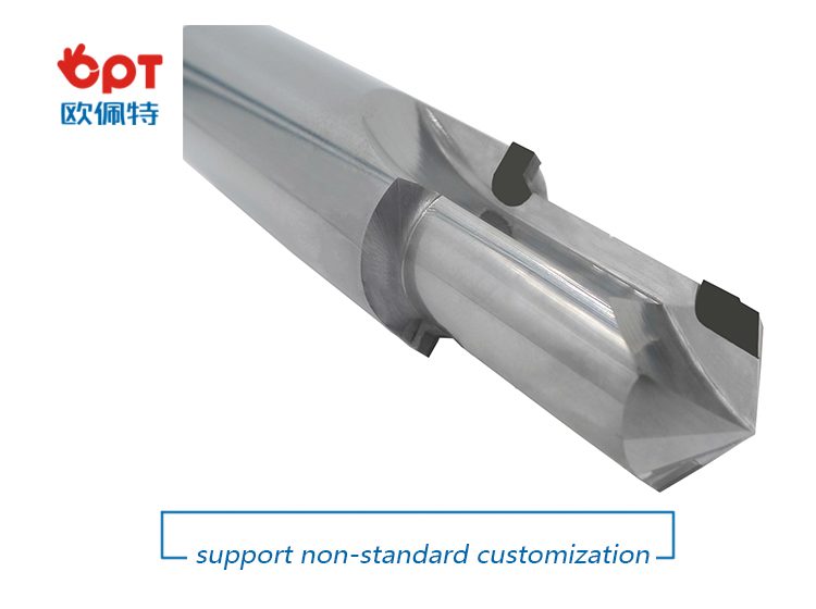
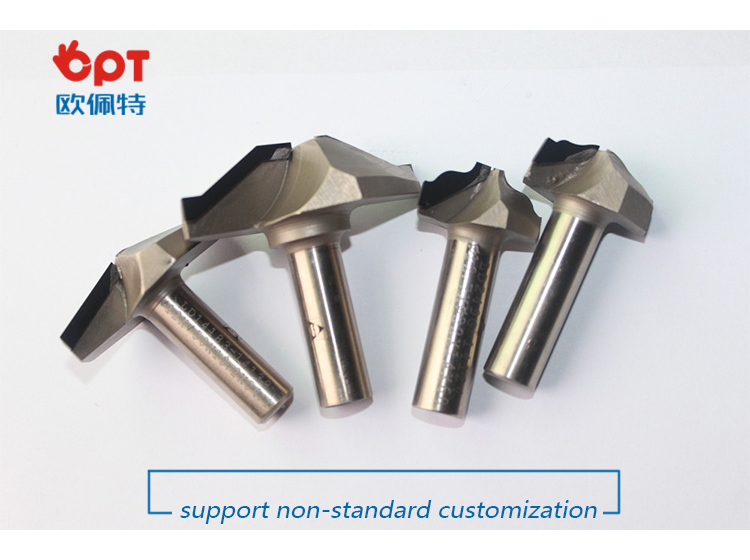
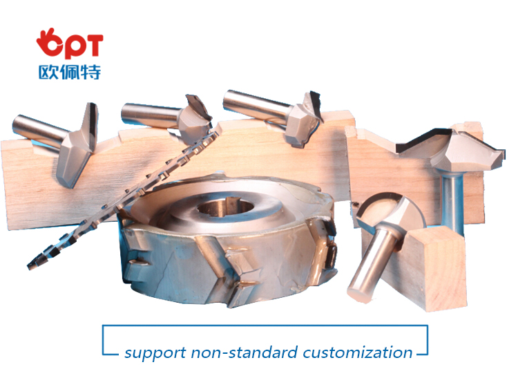
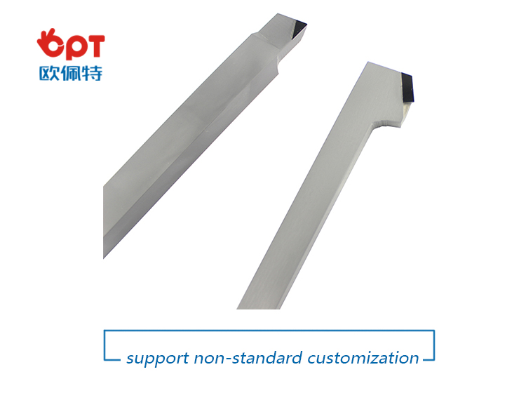


PRODUCTING PROGRESS:

PAYMENT AND DELIVERY:

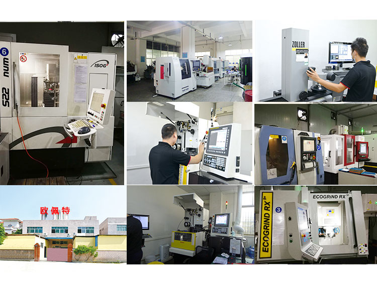
PRODUCT EQUIPMENT :
ABOUT US :
We are specialize in manufacturing PCD diamond tools and Carbide tools. Our major product inclulde PCD Inserts , PCD Reamers , PCD End Mills, PCD Taps, Cabide Inserts,Carbide Drills, Carbide Reams, Taps etc.,
We also offered customized cutting tools per drawings, and provide package according to customer requirements. We manufacture a series range of cutting tools for machining of Cast iron, Aluminium alloy and Non-Ferros metal, it is widely used in all major sectors like Automobiles, Engineering, Aerospace, Aviation and 3C industry. Premium quality of raw material is used in the production and strict examination during processing with advanced equipment, so our client are satisfied with our reliable quality and on-time delivery.
Our best selling of cutting tools include PCD Inserts, PCD End Mill, PCD Ball Nose Mill, PCD Reamer, Carbide Taps , Carbide End Mill, Special Form Cutter and many more. For these years we have been made a large forward in the technologies of manufacturing cutting tools. With high quality on performance and price, our product sells well both on domestic and overseas market. And we will always focus on the quality and best service, to make long business relationship.

quanlity control:
We have dedicated team of quality control and precise equipment to keep good and stable performance for our products and processing services.

Boring Cutter,Lathe Turning Tools,End Mill Drill Bit,Carbide Drill
OPT Cutting Tools Co., Ltd. , https://www.optdiamondtoolss.com