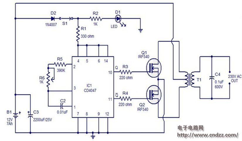
Below is a circuit diagram of a simple 100 watt inverter using integrated circuit CD4047 and MOSFET IRF540. The circuit is simple, low cost, and can even be assembled on a veroboard.
The CD 4047 is a low power CMOS steady state/monostable trigger IC. Here, it is wired as an unsteady multivibrator to generate two pulse sequences. The 0.01S is 180 degrees out of phase with IC pins 10 and 11. The pin 10 is connected to the gate of Q1 and pin 11 to be connected to the gate of Q2. Resistors R3 and R4 can be prevented from being loaded by the ICs of the respective MOSFETs. When pin 10 is high Q 1 conducting, current flows through the positive half of the output AC voltage in the upper half of the primary side of the transformer. When pin 11 is high Q2 conducting, current flows through the lower half of the transformer's primary in the opposite direction, which accounts for the negative half of the output AC voltage.

Traffic Facilities,Waterproof Traffic Facilities,Outdoor Traffic Facilities,Traffic Control Devices
Yangzhou Heli Photoelectric Co., Ltd. , https://www.heli-eee.com