VSYNC: The frame sync signal indicates the start of scanning 1 frame, and one frame is also a picture displayed by the LCD.
HSYNC: Line sync signal, indicating the start of scanning 1 line.
VDEN: Data enable signal.
VD[23:0] : LCD pixel data output port.
VCLK: pixel clock signal.
Register parameters:VSPW: Pulse width of the frame sync signal in units of 1 line.
VFPD: The front shoulder of the frame sync signal, in units of 1 line (Line).
VBPD: The back shoulder of the frame sync signal, in units of 1 line (Line).
LINEVAL: Frame display size -1, that is, screen line width -1. For LCD screen with 800*480 allocation rate, then LINEVAL=480-1=479, please remember that it is the screen width, that is, the LCD screen displays one frame. The number of rows required for the data.
HBPD: The back shoulder of the line sync signal, in units of 1VCLK.
HFPD: The front shoulder of the line sync signal, in units of 1VCLK.
HSPW: Pulse width of the line sync signal in units of 1VCLK.
HOZVAL: The line display size is -1, that is, the screen column width is -1. For the LCD screen with 800*480 allocation rate, then HOZVAL=800-1=799, please remember that it is the screen width, that is, the LCD screen displays one line of data. The number of pixels required.
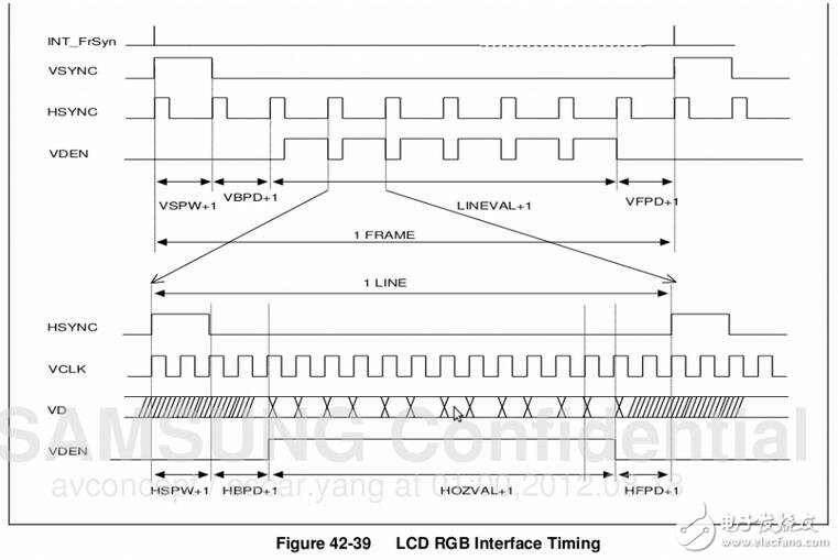
As can be seen from the above figure:
The time required to scan one frame: ((VSPW+1)+(VBPD+1)+( LINEVAL+1)+(VFPD+1)) line time.
The time required to scan one line: ((HSPW+1)+(HSPD+1)+(HFPD+1)+(HOZVAL+1)) VCLK time.
A VCLK time is determined by CLKVAL in the LCD register VIDCON0: PCLK/(CLKVAL+1)
So the time required to scan a frame:
T=[(VSPW+1)+(VBPD+1)+(LINEVAL+1)+(VFPD+1)]*[(HSPW+1)+(HSPD+1)+(HFPD+1)+ (HOZVAL+ 1)]* PCLK/ (CLKVAL+1).
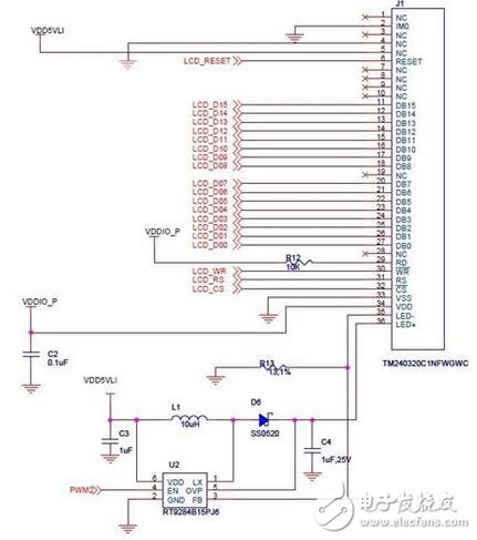
LCD backlight driver design:This backlight driver development corresponds to the IMX233 LCD backlight device, which is mainly composed of three parts: PWM, RT9284B15PJ6 chip and LCD backlight.
PWM (Pulse-Width Modulator) is a very effective technique for controlling analog circuits by using the digital output of a microprocessor.
The RT9284B15PJ6 chip is a highly efficient and highly integrated LED driver equivalent to an LED switch. The schematic diagram of the LCD backlight circuit is shown in Figure 1. The LCD backlight is connected to the two pins of the RT9284B15PJ6 chip, and one of the pins of the chip is connected to the PWM. We mainly indirectly control the brightness of the backlight by generating the waveforms of different effects through the relevant registers of the PWM, so we will mainly introduce the PWM below.
Pulse Width Modulation (PWM) is the use of the digital output of a microprocessor to control an analog circuit. In short, PWM is a method of digitally encoding the level of an analog signal by digitally controlling the analog circuit. The method can greatly reduce the cost and power consumption of the system, so it is widely used in many fields from measurement and communication to power control and transformation.
In a simple circuit with a battery (voltage 5V), incandescent bulb and switch connected, if the switch is closed for 50ms, the bulb will get 5V, then turn the switch off for 50ms, then the bulb will get 0V. If the above process is repeated 10 times in 1 second, the bulb will be illuminated, and the effect seen is exactly the same as that connected to a 4.5V battery. In this case, the duty cycle is 50%. The modulation frequency is 10 Hz. Figure 2 shows two different PWM signals and their corresponding different analog signal values. The voltage is 5V and the duty cycles are 10% and 50% respectively. The two different PWM signals correspond to the analog signals of 0.5V and 2.5V respectively. value.
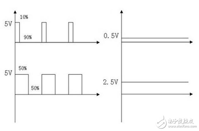
Figure 2 two different PWM signals and corresponding analog signals 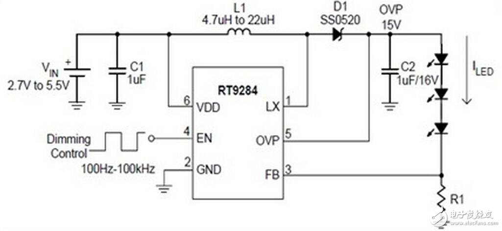
Figure 3 circuit diagram
Figure 3 shows the circuit diagram of the RT9284B15PJ6 chip. We are concerned with the EN pin. Its input is a PWM signal so that the chip can control the brightness of the LED output corresponding to the PWM signal. In the development of backlight driver, the hardware-related part is mainly the PWM register corresponding to the LCD backlight, which will be described in detail later.
ShenZhen Fahold Electronic Limited , https://www.fahold.net