Switching power supply is a kind of power supply that uses modern power electronics technology to control the ratio of time when the switch is turned on and off, and maintains a stable output voltage. The switching power supply is generally composed of a pulse width modulation (PWM) control IC and a MOSFET. Power supply is an indispensable component of various electronic devices. Its performance is directly related to the technical specifications of electronic devices and whether it can work safely and reliably. Since the key components inside the switching power supply work in the high-frequency switching state, the power consumption is small, the conversion rate is high, and the volume and weight are only 20%-30% of the linear power supply, so it has become the mainstream product of the regulated power supply.
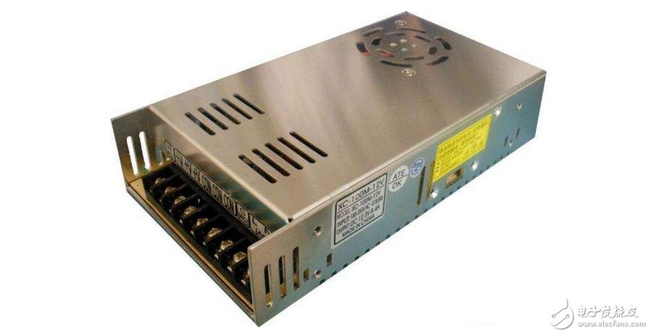
The maintenance of electrical faults in electronic equipment, in the principle of easy to difficult, basically starts with the power supply, after determining that the power supply is normal, and then repairing other parts, and the power failure accounts for most of the electrical failure of the electronic equipment. . Therefore, understand the basic working principle of the power supply at the beginning, familiar with its maintenance skills and common faults, which will help shorten the repair time of electronic equipment and improve the maintenance skills of personal equipment.
The main purpose of switching power supply:Switching power supply products are widely used in industrial automation control, military equipment, scientific research equipment, LED lighting, industrial control equipment, communication equipment, power equipment, instrumentation, medical equipment, semiconductor refrigeration and heating, air purifiers, electronic refrigerators, liquid crystal displays, LED Lighting, communication equipment, audio-visual products, security monitoring, LED light bags, computer chassis, digital products and instruments.

In the field of switching power supply technology, people develop related power electronic devices and develop switching frequency conversion technology. The two promote each other to promote the switching power supply to a lighter, smaller, thinner, lower noise and high reliability. The direction of anti-interference is developing. Switching power supplies can be divided into AC/DC and DC/DC.
Micro low power switching power supply
Switching power supplies are moving towards mass and miniaturization. Switching power supply will gradually replace all applications of transformers in life. The application of low-power micro-switching power supply must first be reflected in digital display, smart meter, mobile phone charger and so on. At this stage, the state is vigorously promoting the construction of smart grids, and the requirements for electric energy meters are greatly improved. Switching power supplies will gradually replace the application of transformers on electric energy meters.
Inverted series switching power supply
The difference between the reverse series switching power supply and the general series switching power supply is that the output voltage of the reverse series switching power supply is a negative voltage, which is exactly opposite to the positive voltage of the output of the general series switching power supply; Inductor L only outputs current to the load when switch K is turned off. Therefore, under the same conditions, the output of the reverse series switching power supply is twice as large as that of the series switching power supply.
The main parameters of the switching power supply:The performance indicators of switching power supplies can be divided into input, output, protection, display and indication functions, system functions, electrical insulation and electromagnetic compatibility, etc.:
1. Electrical performance indicators of switching power supplies.
1 input characteristics: input voltage type and voltage range, grid frequency, harmonic distortion.
The general parameters included in the input section are: input voltage range, input current, input frequency, standby power consumption, inrush current, starting current, PF value, and so on.
Input voltage, power supply is the device for electrical energy conversion. Since the conversion is mentioned, the power provided is also varied. For example, China's mains electricity is 220V 50HZ AC, some countries use 110V 60HZ AC, such as the battery used in the car, the battery voltage is also diverse, 12V 24V 36V, etc., the subway is used 110V The direct current, the communication uses -48V and so on.
According to the general division, the input of the power supply can be roughly divided into a DC input and an AC input, which results in various power input. The nameplate of the power supply that we can see in our life will be marked with an input voltage range: if the part is marked as input 100-240VAC, that is, it is compatible with 110VAC and 220VAC. Sometimes there will be a small switch on the power supply. The wave is over 110VA AC, and the switch uses 220VAC AC. This switch can't be undulated, please see the picture:
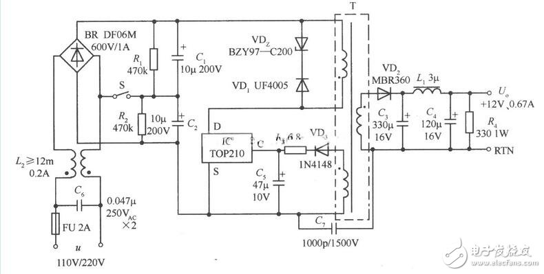
The switch S on the figure functions as a dual voltage switch. Its function is to double the voltage through the switch at 110VAC input to reach the normal working voltage of the DC voltage of the main power part during design, so that the power supply works. Normal. When the 220VAC input is made, the switch is turned off, and the voltage at this time is also the operating voltage of the DC high voltage part of the design. If the 220VAC input, we close the switch, so that the voltage doubles, the DC high voltage part of the voltage will be twice the design, so the power supply will be damaged. The purpose of this is to be compatible with both 110VAC and 220VAC voltages at a lower cost. The disadvantage is that you must confirm the input voltage when you change the area of ​​use, and you cannot switch the error.
For those without a voltage switch, the nameplate also identifies the input voltage: 100VAC-240VAC, which is an adaptive power supply without manual intervention.
There is also the power supply in the factory test, the input voltage of the test will be wider than the nameplate identification, generally identifies 100VAC-240VAC, the test range is 85-265 or 90-264, of course, the test frequency will also be on the nameplate The 50-60HZ is somewhat wider and is: 47-63 (maximum) or 47-440 (less).
Some nameplates indicate the input: 110VAC or 220VAC. This is a single power supply for a certain country or region. It cannot be exchanged. It is not used according to the nameplate. If the power supply does not work, the power supply will be damaged. The marking is 110VAC, the general test range is 85-165VAC, the marking is 220VAC, and the test range is generally 175-265VAC.
2 Output characteristics: rated output voltage, rated output current, voltage regulation accuracy (voltage regulation and load regulation), transient response, output ripple voltage and ripple current, output noise voltage.
The output part mainly includes: output voltage and output voltage accuracy, rated output current, load effect, source effect, startup delay time, shutdown hold time, boot overshoot voltage, output ripple and noise, capacitive load capacity, dynamic response (over Rushing amplitude and recovery time), efficiency, etc.
The DC input current of the power supply device is required. Like our common mobile phone direct charge, charger, stupid charge, computer power supply, notebook adapter, MP3 charger, etc., etc., will mark an input current, then how do we understand this value? What?
(1) Let's first look at the power supply of the DC input. What is the concept of the current value marked?
When it comes to DC power supply, it also has a DC voltage input range. If the car charger is compatible with most vehicles, it will make a wide range of input voltages of 9-36V, so that the 12V battery pack is still a 24V battery pack. This charger can be applied. The current marked on it should first satisfy the rated power output, and the rms value of the input current at the lowest input (here, 9V input voltage). At this time, the rated output power is divided by the efficiency at this time divided by the input voltage. This is the effective value of the input current at this time. Of course, the value marked on the nameplate will definitely be much larger than this value. Why is this?
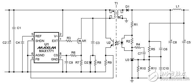
Let's look at the input end of the power supply. There is a large capacitor C2. Before the power is turned on, this capacitor has no voltage. After power-on, the capacitor is equivalent to the short-circuit state in an instant. The current at this moment is the inrush current, usually there will be The input current is several times or several times. In order to suppress this state, there is a thermistor that increases the negative temperature coefficient at the input portion as a method of suppressing the inrush current, and there are other circuits. Each has its own advantages and disadvantages.
In addition to capacitors, there are varistor and transient snubber diodes that generate large currents while absorbing surge voltages:
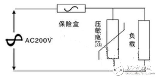
Although this figure is a real input voltage is AC, the effect is the same as DC.
The current conditions generated during absorption are as follows:
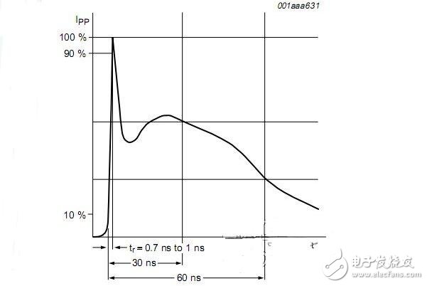
This current value is also reflected in the input current.
In addition to the above points, there is the starting current: the starting current, as the name suggests, is the input current generated by the power supply when the output is started. We can imagine that there is no output at the moment the power is turned on. Because you are powered on, the output of the control circuit is only a little bit established. In the process of establishing, if there is no soft-start circuit, the control circuit will establish the output at the highest speed, knowing that the output is normal. A state of balance. It is this process of establishment that also produces a large starting current. If the soft-start circuit is OK, the starting current will be small, even smaller than the stabilized current.
(2): Input current marked on the nameplate of the AC input power supply
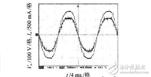
The input current marked on the AC input power nameplate is somewhat different from the DC condition. It also takes into account another input parameter: the PF value. PF refers to the input power factor. In the absence of power factor correction, the waveform is as follows
After power factor correction, the waveform is as follows:
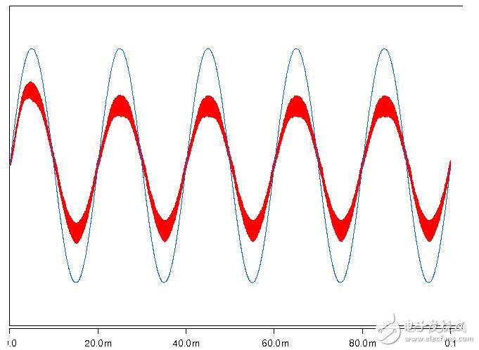
We can clearly see that in the first picture, the voltage and current are different in phase, which will increase the reactive power and increase the input current. The corrected voltage and current phases are basically the same, and the input current will be relatively small. This is one of the reasons why the input current calculated by our parameters on the power supply nameplate is much smaller than that indicated on the nameplate.
Based on the above description, we can know that the input current is mainly determined by those factors. In this way, when we choose the fuse, we will consider more, whether it meets the minimum voltage input and the current value calculated by the highest power output.
3 electrical insulation. The electrical insulation of the switching power supply is an important part of the safety index. The factory switching power supply must pass the electrical insulation test before it can be put into the market. Electrical insulation test and leakage current test of the AC input terminal to the DC output terminal.
4 control mode and control functions: voltage type control mode, current mode control mode, external shutdown function, remote remote control function, numerical control function.
5 Protection function: The switching power supply must have perfect protection measures. The common protections are over current protection, short circuit protection, over voltage protection, reverse polarity protection and over temperature protection. Input and output voltage and current monitors, protection relays, alarms, automatic/manual reset circuits, etc. can also be added if necessary. The electromagnetic compatibility test of the prototype should also be carried out under conditions.
2. Mechanical performance indicators. Volume, weight, etc.
3. Environmental working conditions. Ambient temperature, storage temperature, relative humidity, height, heat dissipation conditions (natural cooling, fan cooling), etc.
4. Reliability indicators. Reliability metrics are usually expressed in terms of Mean TIme Between Failures (MTBF). The MTBF should generally be greater than 100,000 hours. The input, output, protection, electrical insulation and electromagnetic compatibility in the switching power supply are the basic requirements of the power supply. The display and indication functions and system functions are special requirements for communication. In the general power supply specification, there are environmental conditions, structural dimensions and quality of the power supply, which determine the cooling and structural design of the power supply and the selection of components. The power supply designer must fully study the above conditions. The design process implements the technical specifications from beginning to end, and fully considers the production cost and manufacturing method of the developed switching power supply, and the designed switching power supply can be successful. Therefore, product design is different from theoretical research, and the advanced circuit here is far from enough. Products should adopt mature advanced circuit technology, the lowest production cost, including device, manufacturing, structure, labor, equipment, etc., up to maintenance costs, while achieving the highest reliability. Such products can survive.
5. Cost index: Under the premise of ensuring performance indicators, the cost of switching power supply should be reduced as much as possible to improve its cost performance and create conditions for commercialization.
JUUL VAPE PEN, Wholesale Juul , Juul manufacture
Shenzhen Xcool Vapor Technology Co.,Ltd , https://www.szxcoolvape.com