The use of white LEDs has enabled flash to enter newer applications, and its reliability, durability, and power control of white LEDs make these devices attractive. When using incandescent lamps, the power management of the device is simply a switch. However, white LEDs cannot be operated directly from the battery in the flash because it requires a voltage between 2.8V and 4V, compared to a battery voltage of only 1.8V to 3V. The complexity of power management has increased because the light output of white LEDs is related to current, while the characteristics of white LEDs exhibit an extremely nonlinear relationship with voltage. One way to solve this problem is to increase the current limiting capability of the power supply.
The circuit for driving the white LED with the boost power regulator is shown in Figure 1. Increase the power regulator TPS6200&TImes; can generate the high voltage required for white LEDs. The internal boost power stage connects the VIN and PGND terminals to provide current to the output pin L. This circuit works by turning on the output switch so that the battery voltage on inductor L1 can be connected. Once the inductor L1 has stored enough energy, the output switch is immediately turned off. The inductor current drives the switching node to switch to the negative and the energy at the input is transferred to the output capacitor C1.
Since the switches at the output and input are MOSFETs, the voltage is reduced to the diode scheme, resulting in high efficiency. Regulator TPS6200&TImes; The resistor can monitor the current flowing through the white LED, and compare the detection voltage with the internal 0.45V reference voltage to achieve the adjustment function. Therefore, current and illuminance are functions of the sense resistor voltage. Although the internal reference voltage of the TPS6200&TImes; is lower than that of most other converters, it also causes power loss. When using a white LED voltage of 2.8~4V, its efficiency will be reduced by 10%~14%. This loss should be reduced by lowering the resistance of the resistor and using an amplifier to achieve a low voltage.
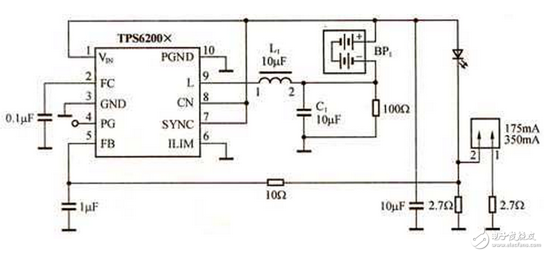
Figure 1 Scheme for boosting the power conditioner to drive white LEDs
Figure 2 shows the efficiency curve of load current regulation and boost voltage at a current regulation point of 350 mA. In the normal battery voltage range, the operating efficiency can reach more than 80%, but as the battery voltage drops to the end of life value, the efficiency will decrease. In addition, Figure 2 also illustrates the presence or absence of the effect of the sense resistor. When the input voltage is high, the efficiency is close to 95%, and when the input voltage is low, the efficiency is reduced to 80%. The trend of the curve is derived from two related effects: one is that the input current and the switching current are lower at high input voltage, so the conduction and switching losses are lower; the second is very similar to the autotransformer, the boost power stage is not processed. Total input power. The amount of power processed by the power stage is related to the boost voltage or to the voltage difference between the input voltage and the white LED voltage.
In this design, the voltage of the white LED is approximately 8.7V, so on a high voltage line of 8.2V, the power stage only processes 6% of power [(8.7-8.2)/8.7]. On low-voltage lines with much higher currents, the power stage has to handle 4 times the power at 8.2V, or 24%.
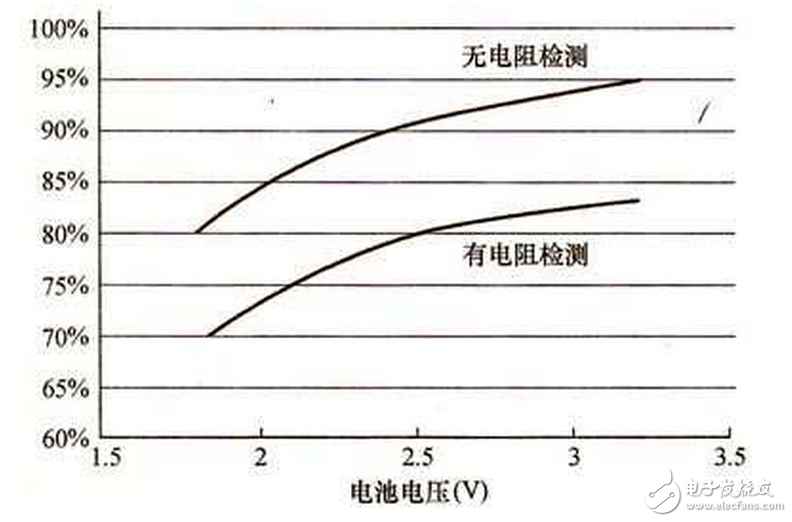
Figure 2 Efficiency curve of the circuit
2, white LED control circuitWhite LEDs are current-driven devices, and the light output intensity is determined by the current flowing through the LED. Figure 3 shows a simple bias circuit consisting of a voltage source and a current limiting resistor. The current flowing through the white LED is determined by:
IDIODE=(VCC-VF)/(RLIM+RDS(ON)) (1)
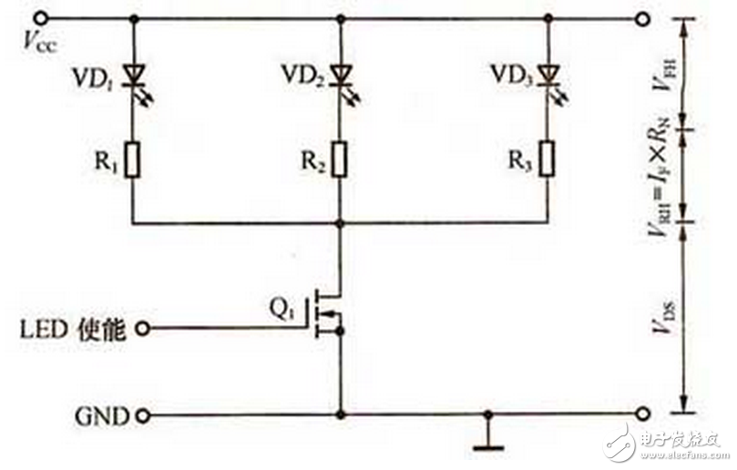
Figure 3 LED bias circuit
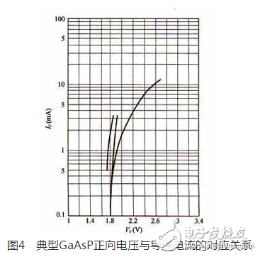
The cost of this method is lower, but the forward voltage VF of different diodes is required to be consistent. 4 and 5 show the relationship between the forward voltage (typical value) of the white LED and the on current at 25 °C. It can be seen from the current index that for GaAsP white LEDs, VF can rise to 2.7V (+40%); for InGaN white LEDs, VF can rise to 4.2V (+20%). If multiple white LEDs are needed in the system, such as 8 white LEDs for the mobile phone back panel display, multiple current limiting resistors will be required according to the design scheme of Figure 6, occupying a large circuit board area.
The basic structure of an LED is a semiconductor P-N junction. Experiments have shown that when current flows through the LED component, the temperature of the P-N junction will rise. In the strict sense, the temperature of the P-N junction region is defined as the LED junction temperature. Usually because the component chips have a small size, we can also regard the temperature of the LED chip as the junction temperature.
2. What are the reasons for the LED junction temperature?When the LED is working, there are five conditions that can cause the junction temperature to rise to different degrees:
a. The electrode structure with poor components, the material of the window layer substrate or the junction region, and the conductive silver paste have a certain resistance value, and these resistors are mutually added to form a series resistance of the LED element. When a current flows through the P-N junction, these resistors also flow through, causing Joule heat, which causes an increase in chip temperature or junction temperature.
b. Since the P-N junction cannot be extremely perfect, the injection efficiency of the component will not reach 100%, that is to say, in the operation of the LED, in addition to the injection of charges (holes) into the N region, the N region will also Injecting a charge (electron) into the P region, in general, the latter type of charge injection does not produce a photoelectric effect, but is consumed in the form of heat. Even if the useful part of the injected charge does not become all of the light, some of it combines with the impurities or defects of the junction and eventually becomes hot.
c. Practice has proved that the limitation of light extraction efficiency is the main reason for the rise of LED junction temperature. At present, advanced material growth and component manufacturing processes have enabled most of the input electrical energy of LEDs to be converted into optical radiant energy. However, due to the much larger refractive index of the LED chip material compared to the surrounding medium, the poles generated inside the chip are generated. Most photons ("90%") fail to overflow the interface smoothly, and total reflection occurs on the chip and media interface, returning to the inside of the chip and being absorbed by the chip material or substrate through multiple internal reflections, and is changed in the form of lattice vibration. Heating causes the junction temperature to rise.
d. Obviously, the heat dissipation capability of LED components is another key condition for determining the junction temperature. When the heat dissipation capability is strong, the junction temperature drops. Conversely, when the heat dissipation capability is poor, the junction temperature will rise. Since the epoxy adhesive is a low thermal conductivity material, the heat generated at the P-N junction is difficult to dissipate into the environment through the transparent epoxy, and most of the heat passes through the substrate, the silver paste, the envelope, and the epoxy bonding layer. The PCB and the heat sink diverge downward. Obviously, the thermal conductivity of the relevant material will directly affect the heat dissipation efficiency of the component. A common type of LED, the total thermal resistance from the P-N junction region to ambient temperature is between 300 and 600 ° C / w. For a power LED component with good structure, the total thermal resistance is about 15 to 30 ° C. /w. The large difference in thermal resistance indicates that ordinary LED components can only operate normally with a small input power, while power components can dissipate power up to the watt level or higher.

a, reduce the thermal resistance of the LED itself;
b, a good secondary heat dissipation mechanism;
c. reducing the thermal resistance between the LED and the installation interface of the secondary heat dissipation mechanism;
d, control the rated input power;
e, reduce the ambient temperature
The input power of the LED is the only source of thermal effect on the component. A portion of the energy becomes radiant light energy, and the rest is eventually turned into heat, which raises the temperature of the component. Obviously, the main method to reduce the effect of LED temperature rise is to try to improve the electro-optical conversion efficiency of the component (also known as external quantum efficiency), so that as much input power can be converted into light energy. Another important way is to improve the components. The heat dissipation ability causes the heat generated by the junction temperature to be dissipated into the surrounding environment through various channels.

Vapesoul & Voom series Vape are so convenient, portable, and small volume, you just need to take them
out of your pocket and take a puff, feel the cloud of smoke, and the fragrance of fruit surrounding you. It's so great.
We are the distributor of the Vapesoul & Voom vape brand, we sell vapesoul disposable vape,vapesoul vape bar, voom vape disposable, and so on.
We are also China's leading manufacturer and supplier of Disposable Vapes puff bars, disposable vape kit, e-cigarette
vape pens, and e-cigarette kit, and we specialize in disposable vapes, e-cigarette vape pens, e-cigarette kits, etc.
Vapesoul & Voom Vape Disposable Vape Pen E-cigarette Fruit Flavor Series
Ningbo Autrends International Trade Co.,Ltd. , https://www.supermosvape.com