The intelligent alarm system makes full use of the existing telephone network for design, and uses the telephone keyboard operation circuit, the ringing identification circuit, the remote message circuit, the automatic identification of the main called off hook circuit, the dual tone dialing (self ringing) circuit, etc., to solve the alarm. Not timely, false negatives, false positives, etc., and can improve the call completion rate. It is mainly used for burglar alarms in homes, shops, offices, and places with valuables.
Smart phone alarm hardware design
Main circuit design
1, dial circuit
The dialing circuit uses the HT9170 and HT9200A as dual-tone multi-frequency (DTMF) signal receivers and generators, respectively. The automatic dialing chip adopts the serial DTMF dialing chip HT9200A, receives the telephone number sent by the CPU and sends a dual tone multi-frequency signal to the telephone line to establish a connection between the calling party and the called user. Each output frequency of the HT9200A is determined by a combination of different bit codes of 5 bits (D4 to D0). When the chip select signal CE is low, the CPU serially inputs 5-bit code to the data input terminal DATA of the HT9200A through the P0.5 port, latches the data on the falling edge of CLK, and transmits the signal from the output terminal DTMF through the analog switch. The line carries the dial signal of the DTMF tone.
Signal Generator HT9200A
The HT9200A is a serial DTMF signal generator with good temperature adaptability and an operating temperature range of -20 to +70 °C in an 8-pin DIP or SOP package.
Signal Receiver HT9170
The HT9170 integrates a digital decoder and a dual-tone DTMF receiver with filter function to operate in power-down mode and suppression mode. The HT9170 uses a digital calculation method to identify 16 times of DTMF audio decoded into a 4-bit code output. The high-precision conversion capacitor filter separates the audio DTMF signal into a low-frequency signal and a high-frequency signal, and the self-contained dialing audio blocking circuit can eliminate the blocking circuit required by the pre-filter.
2, automatic pick up machine circuit
The automatic pick-up circuit is shown in Figure 1. It consists of a triode inverting amplifier circuit and a relay. The system detects the signal level from 0 to 3.5 V. When the system detects the alarm signal, the main control system makes PICK high level, the triode is turned on, the relay is closed, K1 is turned on, and the system automatically picks up the machine. After the user completes the command operation (such as after the external alarm process is completed), the main control system gives PICK a low level, the triode is turned off, the relay is released, the switch K1 is disconnected, and the machine is automatically hung up.
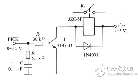
Figure 1 Automatic hook off circuit
3. Signal sound detection circuit
The dialing tone of the telephone system, the ringing tone and the busy tone have an average frequency of 450 Hz (±25 Hz), but the discontinuous ratio is different, and there is a significant difference in time (the dial tone is 450±25 Hz continuous signal, the busy tone is 0) .35 s pass, 0.35 s off, ringback tone is 1 s pass, 4 s off). Therefore, the signal tone is an analog signal. The signal tone detection circuit needs to complete the analog to digital conversion. The signal detection circuit is shown in Figure 2. The photocoupler is used to detect the signal, the resistors R1 and R2 are used for voltage division, and R3 and D are used for shunting. The parameters of each component are shown in the figure. The signal is outputted by the optocoupler and the negative pulse signal is output. The output is processed by the inverter 74LS19 with Schmitt trigger, and converted into a digital signal for the main control system to count.
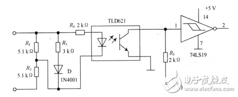
Figure 2 signal detection circuit
The counting time is 5 s, the lower limit of the dial tone is (450-25) & TImes; 5 = 2 125, the upper limit of the count is (450 + 25) & TImes; 5 = 2 375, that is, the counting range is 2 125 ~ 2 375. Similarly, the busy tone count range is 1 041 to 1 212, the ring back tone count range is 425 to 475, and the no tone sound count should be 0. Therefore, the system uses the intermediate value of the adjacent counting limits of different tones to distinguish different tones.
4, alarm signal detection circuit
The alarm signal detection circuit is shown in Figure 3. This system uses AMN pyroelectric infrared sensor for detection. Use the better performance OP-07 to amplify the signal, use a single power supply, the amplification factor is set to 10 (Au=R2/R1=10). When someone enters its detection range, the sensor's No. 2 pin outputs the forward level. After being amplified, an alarm start signal is generated and sent to the main control circuit.
The alarm has the characteristics of automatic, fast and accurate. When the alarm occurs, it can automatically dial 110, and the other party automatically plays the recorded voice alarm content after picking up the phone. If the other party is busy, it can automatically pick up the hook and automatically cycle in the order of dialing, detecting and playback. The alarm has the characteristics of automatic, fast and accurate. When the alarm occurs, it can automatically dial 110, and the other party automatically plays the recorded voice alarm content after picking up the phone. If the other party is busy, it can automatically pick up the hook and automatically cycle in the order of dialing, detecting and playback.
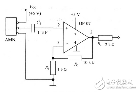
image 3 Alarm signal detection circuit
Edit Comment: The text briefly introduces the circuit design of the smart phone alarm system. It has the characteristics of automatic, fast and accurate. When the alarm occurs, it can automatically dial 110, and the other party automatically plays the recorded voice alarm content after picking up the phone. If the other party is busy, it can automatically pick up the hook and automatically cycle in the order of dialing, detecting and playback.
Electronic enthusiasts "Security Technology Special Issue", more quality content, download now

KNLE2-63 Residual Current Circuit Breaker With Over Load Protection
KNLE2-63 TWO FUNCTION : MCB AND RCCB FUNCTIONS
leakage breaker is suitable for the leakage protection of the line of AC 50/60Hz, rated voltage single phase 240V, rated current up to 63A. When there is human electricity shock or if the leakage current of the line exceeds the prescribed value, it will automatically cut off the power within 0.1s to protect human safety and prevent the accident due to the current leakage.
leakage breaker can protect against overload and short-circuit. It can be used to protect the line from being overloaded and short-circuited as wellas infrequent changeover of the line in normal situation. It complies with standard of IEC/EN61009-1 and GB16917.1.
KNLE2-63 Residual Current Circuit Breaker,Residual Current Circuit Breaker with Over Load Protection 1p,Residual Current Circuit Breaker with Over Load Protection 2p
Wenzhou Korlen Electric Appliances Co., Ltd. , https://www.korlen-electric.com