The Radio Frequency IdenTIfica (TIR) ​​system consists of a reader and an electronic tag. The antenna is a bridge between the reader and the electronic tag. In order to maximize the absorption of the RF energy emitted by the reader by the passive tag antenna, the theory requires that the impedance of the tag antenna and the tag chip be conjugate matched. That is, the impedance value of the UHF band passive RFID single chip directly determines the design of the electronic tag antenna, thereby affecting the performance of the electronic tag.
The UHF band passive RFID electronic tag works on the principle of reflection modulation. The principle determines that the impedance of the electronic tag chip has UHF frequency band, passive, time-varying, nonlinear and other complex characteristics, especially for a single chip with a size of less than 1 mm2. There are difficulties such as small size and RF influence, which makes it difficult to accurately test the impedance of the electronic tag chip by conventional test methods. In this paper, the UHF passive single-chip impedance test method is studied. The test method is tested by the standard chip impedance test.
1 Test principleFor the UHF band passive electronic tag operating characteristics, since the single chip operates in the UHF band, any lead through the tag chip pad will generate parasitic capacitance or parasitic inductance, thereby affecting the chip impedance test. At the same time, using the conventional test method, the length and width of the lead are difficult to grasp, and the repeatability of the test is poor, which is not conducive to accurate testing of the impedance of the tag chip. In this paper, the impedance of the chip is tested by the transmission line impedance matching network, which solves the problems of access difficulties in actual testing.
According to the distributed parameter circuit theory, in the UHF band, the width and length of the transmission line affect the characteristic impedance value of the transmission line. For example, the parallel double wires used in this paper have a wide operating band and can be used in all frequencies below 1 GHz. The characteristic impedance values ​​of parallel two wires [3] are as shown in equation (1):
![]()
Where a is the distance from the center of the parallel two conductors and b is the width of the single conductor of the parallel two conductors.
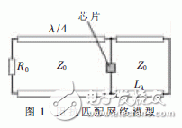
Using the characteristics of the transmission line, a transmission line impedance matching network model is constructed, as shown in Figure 1. The left end is the front-end circuit of the matching network, the input energy is the minimum power consumption under the normal working state of the chip, and the reference impedance can be replaced by a resistor R0 with an impedance of 50 Ω. The λ/4 transmission line of the open terminal is equivalent to a short circuit, and the impedance transformation is realized. A short-circuited short-circuited stub is connected in parallel at the end of the λ/4 transmission line, and this stub is equivalent to an inductive component. The chip is generally capacitive, and is connected in parallel at the end of the λ/4 transmission line. By changing the distance Lλ between the stub terminal and the chip, the inductive reactance introduced by the stub can be changed, and the conjugate matching with the chip impedance is achieved. When the chip and the matching network reach the conjugate matching state, the return loss S11 at both ends of the chip is the smallest, that is, the chip absorbs almost all the energy transmitted by the front-end circuit, and is the minimum energy for normal operation. By observing the value of the return loss S11, to determine the optimal transmission line impedance Z0 and the length of the stub distance chip Lλ, and pushing back the impedance network at this time, the input of the passive RFID tag chip in the working state can be obtained. impedance.

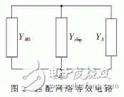
Figure 2 shows the equivalent circuit of the impedance matching network. YR0 represents the input admittance of the resistor R0 after the λ/4 transmission line transformation, Ys represents the input admittance of the short-circuited short-circuit at the chip connection, and Ychip represents the input and output of the chip. . Ychip is connected in parallel with YR0 and Ys. According to the transmission line related theory [4]:


The actual test model is shown in Figure 3. The reader and the adjustable attenuator are connected by a coaxial line, and the output reference impedance is 50 Ω. Run the reader and set its frequency to 915 MHz. By adjusting the adjustable attenuator, reduce the energy of the input impedance matching network, and adjust the transmission line impedance Z0 and the distance from the chip to the chip Lλ, so that the chip can get normal. The minimum energy of work. At this time, the values ​​of Z0 and Lλ are substituted into equation (8) to obtain the impedance value of the chip at the lowest power consumption.

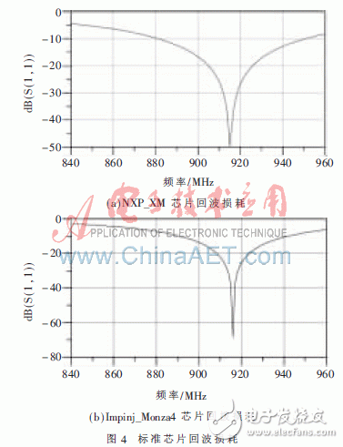
The impedance test model is simulated by ADS simulation software. The tag chip interface is represented by Term1, the output impedance can be set according to the standard impedance of the chip; the output interface after the reader and the attenuator are connected in series is represented by Term2, and the output impedance is 50 Ω; The transmission line model of length λ/4 is represented by TL1 with an angle of 90 deg and a characteristic impedance of Z0. At 915 MHz, the impedance value of Term1 is used with NXP_XM chip data-
When the impedance value specified by sheet is 18.1-149*j, the optimal impedance Z0 is 250 Ω.
It can be seen from the return loss simulation graph of the standard chip shown in Fig. 4 that the standard chip and the impedance matching network have reached a relatively good matching state, which proves that the test principle is effective.

The test board was fabricated based on the above simulation. Combining the chip package form and the width of the SMA head, the center distance of the parallel double line is selected to be 4.15 mm. Using the formula (1), the parallel double line width b value and the corresponding Z0 value are calculated as shown in Table 1, according to Table 1. The calculated value can be used to make a test board. In order to improve the anti-interference ability of the test board, the SMA head first passes through a balun to convert the unbalanced signal into a balanced signal, and then connects to the parallel double-conductor at the back end.

The test board material will have an effect on the wavelength of the transmission line. In combination with the transmission line theory, for the open-ended transmission line, when the test board is used to test the standard chip operating at 915 MHz, the optimal Z0 and Lλ values ​​are obtained. Substituting into equation (8), the impedance of the NXP_XM chip is 17.1-j145; the impedance of the Impinj_Monza4 chip is 10.2-j142 Ω. The impedance of the NXP_XM chip given by the datasheet is: 18.1-j149; the impedance of the Impinj_Monza4 single-port connection chip is: 11-j143 Ω. The impedance value obtained by testing the standard chip is slightly different from the datasheet of the chip.
The causes of the error are as follows: (1) The impedance values ​​of any chip are discrete, which is determined by the quality of the chip itself. The test is only an individual test on the standard chip, and the result given by the datasheet is certain. The number of chip impedances is taken as the average. (2) It can be seen from the simulation that the slight deviation of the distance between the stub and the chip will affect the impedance of the chip, and the average of the multiple readings can be used to reduce the error. (3) As a general-purpose test board, the transmission line impedance value may deviate from the value required for the chip test, but after calculation, it is found that the influence is not large, and the lower return loss value can still be guaranteed.
This paper proposes an impedance test method for UHF band passive RFID tag chip under the lowest power consumption state. The test method is simple, accurate and practical. The test method is used to test the impedance of the chip operating at a single frequency point, and at the same time, the multi-frequency point test can be used to measure the variation of the impedance value of the chip in one frequency band. In addition, the test method introduced a balun in the test board, which improved the anti-interference ability of the test board. This new UHF passive single-chip impedance test improves the deficiencies of traditional test methods and improves the accuracy of the test, laying the foundation for impedance testing in the next band.
AC (Alternating Current) Power cord is to transmit high voltage. It is used to drive machinery or home appliances. Since AC Power Cord is output of high voltage electric power, there is a risk of electric shock injury, therefore, All the AC power cord must comply with safety standard to produce. DC (direct Current) power cord is used to the applicance with lower voltage mostly, so safety requirement is less stringent.
Power Cable, battery cable, DC power cable, AC power cable, power cord
ETOP WIREHARNESS LIMITED , https://www.oemmoldedcables.com