In order to avoid interference with the machine during transmission, we have adopted half-duplex communication. The so-called half-duplex communication refers to that the master and slave can perform two-way communication, but not simultaneously. At the same time, either the master transmits and the slave receives; or the slave transmits and the master receives. In fact, although the center frequency of the receiving carrier of the general infrared receiving module is 38KHz, its receiving frequency is actually very wide, and it can be correctly received and demodulated from 30KHz to 60KHz. Therefore, it is difficult for the master and slave to use different carrier frequencies to achieve full-duplex communication unless an infrared receiving circuit with better frequency selection characteristics is used. In the infrared transmission process, negative logic is used, that is, infrared means logic 0, and no infrared means logic 1. The infrared receiving module is usually at a high level, and it becomes a low level when the infrared signal is received.
How to increase the transmission distance? There are two methods: one method is to use a high-sensitivity infrared receiving circuit, but its cost is relatively high, and it is relatively susceptible to interference. Another method is to increase the transmit power (referring to the peak power, it is not necessary to increase the average power). This can be achieved by reducing the resistance R connected to the transmitter, which can usually be reduced to 10Ω. However, it should be noted that in this case, in order to reduce power consumption and interference with other infrared devices, the duty cycle of the infrared carrier needs to be reduced. Generally choose a duty ratio of about 30%, that is, the high time of DATCLK should be about 18uS, and the low time should be about 8uS (38KHz carrier frequency)
two. PC infrared receiving principle
1. Brief introduction of RS232 standard In PC, infrared communication port is generally integrated, but because of its complicated communication protocol, it is inconvenient to interface with MCU. For the sake of simplicity, we use an extension of an infrared receiving circuit on the COM port (RS232 port) of the PC to achieve. Here, first a brief introduction to the RS232 standard.
RS232 is a serial communication recommendation standard formulated by EIA (Electronic Industry Association), used for the connection between DTE and DCE (typical DTE is PC, typical DCE is modem), the effective transmission distance is 15 meters, if 4 ~ 20mA is used The current loop can reach a communication distance of more than 1 km. In RS232, a total of 25 signal lines (including data lines, control lines, status lines, etc.) are specified, but in actual applications, not all signal lines are necessarily used. In the early PCs, there was usually a 25-pin serial port and a 9-pin serial port; in the PCs produced today, both serial ports use a 9-pin DB9 socket. The signal line definition of the 9-pin serial port is shown in Table 1:
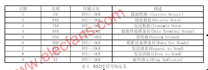
2. Infrared receiving expansion circuit Here we think that DTE is PC, then we can see from Table 1, there are three PC output pins: TXD, DRT and RTS. TXD is a serial data transmission port with a baud rate from 110bps to 115200bps (hardware support required). DTE uses DTR to tell DCE that it is ready to receive data, and uses RTS to request DCE to send data. These two signals are mainly used for hardware flow control. In the infrared receiving extension circuit, flow control is not required, but DTR and RTS are used to provide power for the receiving circuit. We know that the standard RS232 level is negative logic: + 3V ~ + 15V means logic 0; -3V ~ -15V means logic 1. In this way, as long as DTR and RTS are enabled, these two pins can output a level of about + 15V, thereby supplying power to the infrared receiving circuit. According to this design idea, the infrared receiver expansion circuit is shown in Figure 1:
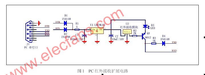
In the above figure, D1, D2 and D4 play an isolation role, R1 is mainly used to protect the PC serial port, C1 and C2 are used for filtering, and U1 is a three-terminal regulator that provides + 5V working power for the infrared receiving module. U2 is a three-terminal integrated infrared receiving module. The general receiving center frequency is 38KHz, which can complete the entire process from infrared receiving, filtering to demodulation. The LED acts as an indicator light, and the LED will flash when an infrared signal is received. The key point of this circuit is the connection of the three pins DTR, RTS and TXD: DTR and RTS are power supply pins, which can provide about 15V of power, provided that they are enabled in the PC monitoring program. The TXD pin provides negative power for reception. The TXD pin is a data sending pin, why can it provide negative power? This is the ingenuity of this circuit. We know that in the RS232 protocol standard, when no data is sent, the TXD pin outputs a low level, that is, about -15V. In the infrared receiving extension circuit, it only has infrared receiving function, but no transmitting function, so it can use the TXD pin to provide low level for receiving. When no infrared signal is received, pin 1 of the infrared receiver module outputs a high level, the transistor Q1 is turned off, and TXD pulls the RXD pin to a low level through D4; when the infrared signal is received, the infrared receiver module outputs a low level , Transistor Q1 turns on, at this time the RXD pin becomes high level.
Coin/Button Cell-retainers And Contacts
Antenk coin cell battery retainers Designed for memory back-up and stand-by applications, these contacts permit quick and easy coin cell replacement and installation. Eliminating "soldered-in" cells, computer, video, telecommunication and similar PCB based product users now have a reliable, "no tools required" method for changing batteries.
Extremely economical, these retainer contacts are available in surface mount (SMT) or thru hole mount (THM) styles for 4.8mm, 6.8mm, 11.6mm,12mm, 16mm, 20mm, 23mm and 24mm coin cells. The THM version has stable mounting legs for excellent board retention during wave solder. The SMT version includes a unique solder tail "flow-hole" design to bolster reflow and strengthen solder joints. They are manufactured from phosphor bronze, precision stamped and are plated with either a high luster nickel finish or matte tin finish ideal for low temperature soldering enviornments. Both feature dual spring contacts to assure reliable connections and a low contact resistance.
Antenk Coin/Button Cell-retainers And Contacts

Coin cell retainers are simple metal contacts that both electrically connect coin cells and hold them in place, while taking up minimal additional space on the PCB. They feature nickel-plating, and since most coin cells have nickel shells this helps to prevent galvanic corrosion, an electrochemical process that can damage dissimilar metals that are in electrical contact. Our retainers are always designed with automation in mind, and can be easily picked and placed, with both through hole and surface mount retainers available for most coin cell sizes. Combining the ease of automation with the low cost of Antenk's retainers, it is no wonder they are such a popular product.
Coin Cell, Button Cell, Retainers, Contacts
Designed for memory backup and standby applications, Antenk's compact coin cell battery retainers permit quick and easy coin cell replacement and installation. By eliminating soldered-in cells, computer, video, telecommunication, and similar PCB based product users now have a reliable, no tools required method for changing batteries.
These holders and retainers are available in surface-mount (SMT) or through-hole-mount (THM) styles for 4.8 mm to 24 mm coin cells. The THM version has stable mounting legs for excellent board retention during wave soldering. The SMT version includes a unique solder tail flow-holedesign to bolster reflow and strengthen solder joints. Both feature dual spring contacts to assure reliable connections and low contact resistance.
Coin Cell, Button Cell, Retainers, Contacts Features
Available in THM or SMT configurations
SMT solder tail with flow-hole design for increased joint strength
SMT solder tail located outside of retainer body which facilitates visual inspection of the solder joints
THM legs maintain relative position during and after soldering
Reliable spring tension assures low contact resistance
Retains battery securely to withstand shock and vibration
Ideally suited for high-density packaging
Ideal for low-profile space-saving PCB applications
Designed for reflow and all PCB soldering applications
Compatible with all wave and reflow operations
Compatible with most vacuum and mechanical, pick and place assembly systems
Matte-tin plate for lower soldering temperatures ideal where other temperature sensitive components are being used
Tin-nickel plated retainers are ideal for lead-free, high-temperature soldering applications
Retainers available for coin cell batteries from 4.8 mm to 24 mm diameter
Coin Cell Retainers by Size of Cell
191 | 335 | CR1025 | CR1216 | CR1220 | CR1225 | CR1632 | CR2016 | CR2032 | CR2320 | CR2325 | CR2330 | CR2354 | CR2430 | CR2450 | CR2477 | F3 iButton | F5 iButton | LR1120 | LR44 | ML414 | SR512SW | SR60 | V80H or CP1654 | BR1025 | BR1216 | BR1220 | BR1225 | BR1632 | BR2016 | BR2032 | BR2320 | BR2325 | BR2330 | BR2450 | BR2477 | Other Sizes
Button Contacts,Coin Cell Retainers And Contacts,Coin Cell Retainers
ShenZhen Antenk Electronics Co,Ltd , https://www.antenkcon.com