With the preparation of the previous two examples, the following project will take you to try to build a MicroBlaze-based application. The privileged classmates also plugged in Xilinx's embedded development platform for the first time and ran a process. As expected, compared with Altera's SOPC Builder (the future push Qsys) and EDS, the development environment is similar. The soup is not changed.
As shown in Figure 1, in fact, when we installed the ISE software, because we chose Embedded EdiTIon (refer to Note 2), then in the installed program menu, as shown in Figure 1, EDK (Embedded Development Kit) Two development platforms, Xilinx Platform Studio (XPS) and Xilinx Software Development Kit (SDK), correspond to Altera's SOPC Builder (or Qsys) and EDS. Because the soft-core MicroBlaze on-chip bus supported by Xilinx SDK is AXI, and Altera's NIOS II is mainly driven by Avalon, there are some differences between them, no matter how good or bad, they are very accustomed to working under SOPC Buider. The environment in which privileged students first came into contact with XPS was really uncomfortable. In contrast, the software platform SDK, because it is an Eclipse-based architecture like EDS, is relatively easy to use, and even the layout and use of menu buttons is somewhat familiar.
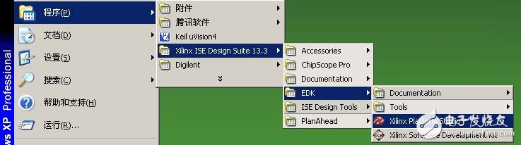
Figure 1 EDK development environment is similar, we are still looking for a fool tutorial to get familiar with the entire development process. Naturally, the privileged classmates will open the DocNav Taotao Gold. As shown in Figure 2, EDK and SDK are all related documents. After a cursory browsing, the privileged students locked in "EDK Concepts, Tools, and Techniques.pdf". Documentation. Although this document is only a simple example of a collaborative development of software and hardware, many design details have been ignored (not let the privileged classmates suffer less), but it can make people feel the big direction, so it takes less time. The privileged classmates successfully built and validated their first embedded project (including hardware engineering and software engineering).
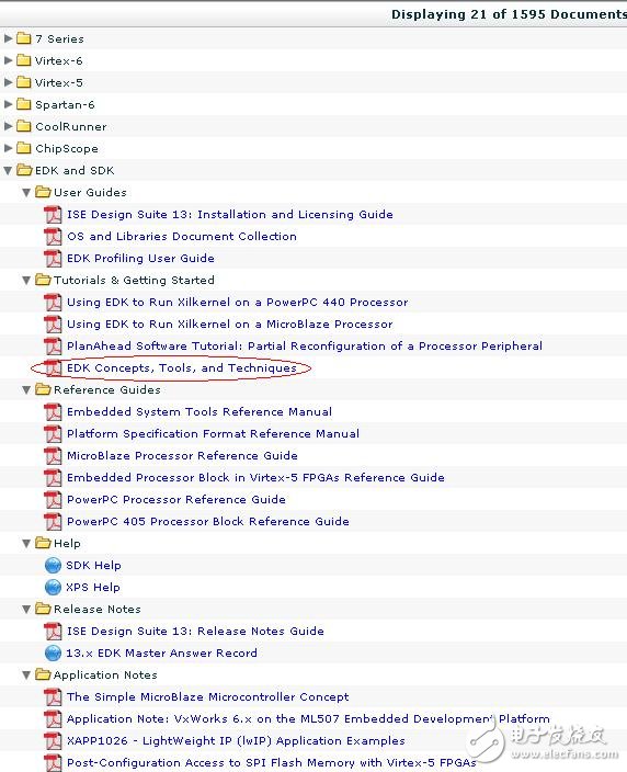
Figure 2 EDK and SDK related documents
As shown in Figure 3, the workflow of the entire software and hardware development is basically illustrated here. From the basic design input of ISE, including the generation of XPS hardware system architecture, and then to the SDK software development, at the same time complete synthesis, constraint, mapping and other compilation steps in ISE, and finally generate downloadable files for board-level debugging verification.
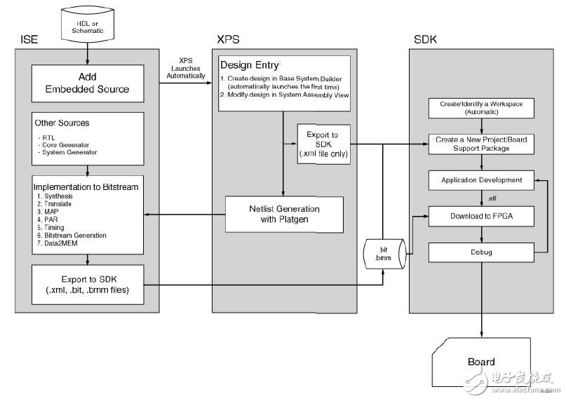
Figure 3 Basic embedded workflow
With the previous development steps, we also simply run the process and experience it. Based on the previous example of the pll project, we then use XPS to add an embedded system with a MicroBlaze soft core. As shown in Figure 4, create a new source file, select Embedded Processor, and name it mysoc.
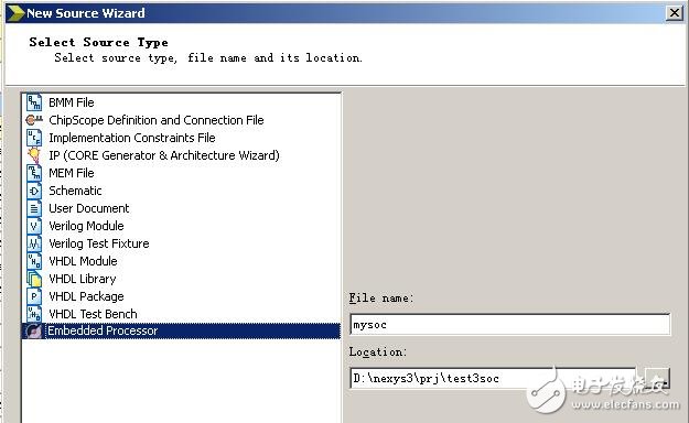
Figure 4 New Embedded Processor File
The newly created Embedded Processor will automatically open the XPS, and then first pop up a basic system wizard selection dialog, as shown in Figure 5. Click on "Yes".
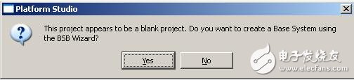
Figure 5 Basic System Wizard Selection
Then the Base System Builder dialog box appears. After selecting AXI system by default, click "OK". Then enter the basic system configuration page, here mainly consists of two pages, the first page is shown in Figure 6. Here, board-level information and system selection, board-level information such as input clock frequency, reset signal effective polarity, etc., system selection can be configured as single-core or dual-core, and the optimization strategy can be area or throughput. Request, no need to change, click "Next" to configure page 2.
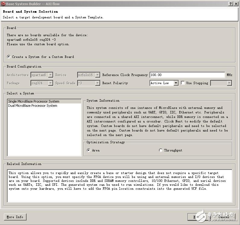
Figure 6 Basic System Settings Page 1 As shown in Figure 7, in the configuration page 2, select Processor Frequency to 50MHz and set the Local Memory Size to 32KB. Next, you need to add an 8-bit GPIO peripheral, click the "Add Device..." button under "Available Peripherals".
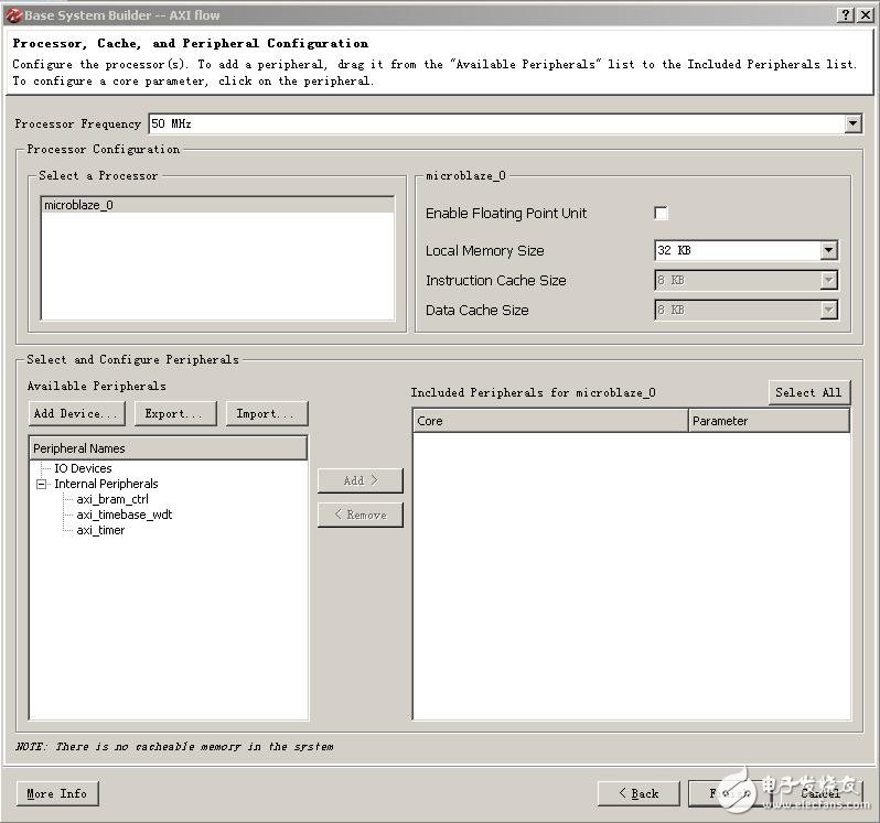
Figure 7 Basic System Settings Page 2 The “Add IO Devices for Generic Board†window pops up. As shown in Figure 8, set “IO Interface Type†to “GPIO†and “Device†to “LEDSâ€. Click “OK†when finished.
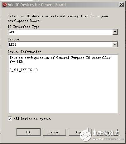
Figure 8 Adding a GPIO Peripheral At this point, the LEDS peripheral shown in Figure 9 appears under “Included Peripherals for microblaze_0â€. The default setting is Data Width 8. Finally we click Finish to complete the wizard configuration.
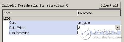
Figure 9. The newly added LEDS peripherals wait for a while. When the new system is generated, as shown in Figure 10, all the components of the new system are listed in the Bus Interfaces list of the System Assembly View that XPS opens by default. And on the left side there is a signal interface connection between the various components. From the interconnection between them, it is easy to understand the architecture of this simple system: microblaze_0 is the famous soft core CPU - MicroBlaze, which connects the AXI bus for peripheral expansion, which is hung on this bus. The peripherals include the GPIO peripheral LEDS that we deliberately added. In addition, the two LMR interfaces of microblaze_0 are connected to microblaze_0_i_bram_ctrl and microblaze_0_d_bram_ctrl respectively. It is inferred from the naming that the two components should be CPU instructions (instrucTIon) and data (data). The storage controller, and the red connection on the right side respectively connect them to the microblaze_0_bram_ctrl component, indicating that this microblaze_0_bram_ctrl is the CPU's main storage controller. In addition, two relatively independent clock_generator_0 and proc_sys_reset_0 generate components for the system clock and reset.
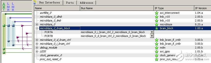
Figure 10 IP component list Next, let's take a look at the Ports section, as shown in Figure 11. Expanding External Ports here is all the pins of the system that need to be directly invisible from the outside. LEDS_TRI_O is the signal that is connected to the on-board indicator, RESET is the active-low reset signal, and CLK_N and CLK_P are the differential signals of a pair of 100MHz inputs. Since our external input 100MHz clock is not differential, but a single clock interface, we need to make some simple modifications. Expand clock_generator_0, right click on the CLKIN column and select “New ConnecTIonâ€. As shown in Figure 12, the differential clock becomes a single clock interface. Mouse down on this single clock signal and right click again and select “Make Externalâ€. This single-ended clock interface appears in the External Ports. The previous differential clock interface did not disappear in the External Ports. You need to right-click and select “Delete External Ports†to delete it.
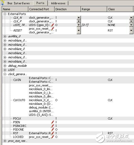
Figure 11 system external connection signal
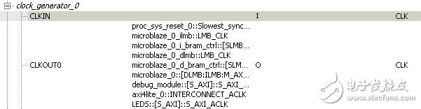
Figure 12 shows the list of External Ports after the changed CLKIN is modified as shown in Figure 13. Figure 13 After the change of the External Ports to complete the clock signal modification, click the XPS menu bar Hardware à Generate Nets to produce the netlist of this embedded hardware system. Go back to ISE and add the mysoc.xmp file under Hierarchy and select it. Expand Design UTIlities under Processes and double-click the instantiation template file for the View HDL Instantiation Template production system, as shown on the right side of Figure 14.
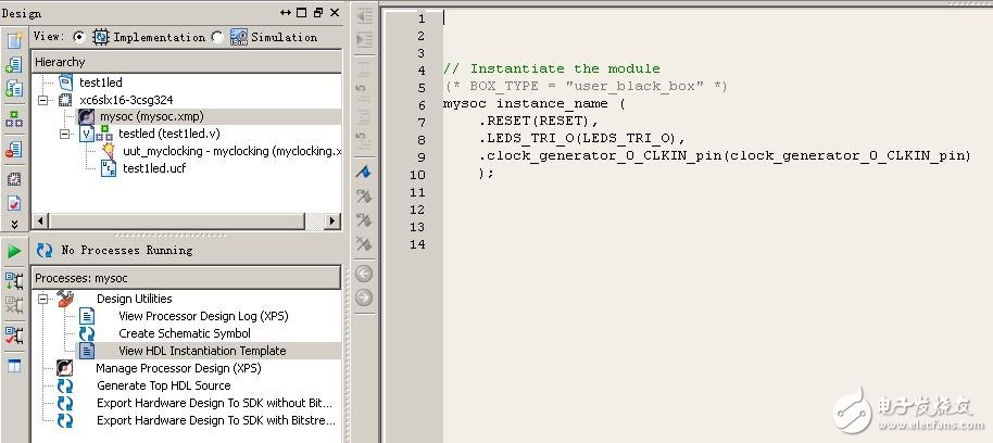
Figure 14 Generate System Instantiation Template Copy this template into the top source code of ISE and match the good interface accordingly. The original 8 LED interfaces will be controlled by software programming. The top source code is modified as follows: module testled( clk,rst_n, led ); input clk; //100MHzinput rst_n; //low level reset signal output[7:0] led; //connected to LED indicator wire clk_100m; / /clocking output 100MHzwire clk_50m; //clocking output 50MHzwire clk_25m; //clocking output 25MHzwire clk_12m5; //clocking output 12.5MHzwire clk_locked; //clocking output completion flag ///------------ --------------------------------------//IP Core Clocking Wizard instantiation ///- --------- Begin Cut here for INSTANTIATION Template ---// INST_TAG myclocking uut_myclocking (// Clock in ports .CLK_IN1(clk), // IN // Clock out ports .CLK_OUT1(clk_100m), / / OUT .CLK_OUT2(clk_50m), // OUT .CLK_OUT3(clk_25m), // OUT .CLK_OUT4(clk_12m5), // OUT // Status and control signals .RESET(!rst_n),// IN .LOCKED(clk_locked) ); // OUT// INST_TAG_END ------ End INSTANTIATION Template --------- //---------------------- -----------------------------// Instantiate my Soc system (* BOX_TYPE = "user_black_box" *) mysoc uut_mysoc ( .RESET(rst_n), .LEDS_TRI_O(led), .clock_generator_0_CLKIN_pin(clk_100m) ); endmodule Finally, we double-click "Generate Programming File" to compile and download the hardware system. generate. Next, we will transfer the platform to the SDK, create a new folder named SDK_workspace in the project directory, and then open a SDK, you need to select a workspace, as shown in Figure 15, corresponding to the SDK_workspace folder.
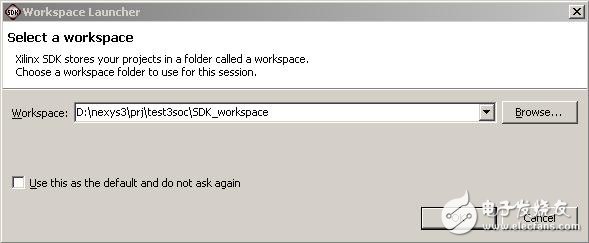
Figure 15 workspace settings After entering the SDK, select Fileà Newà Xilinx C Project on the menu bar, then enter Project name in the "New Hardware Project" and select mysoc\__xps\system.xml in the project directory as the Target Hardware Specification. This configuration page is mainly a hardware platform for setting up software engineering.
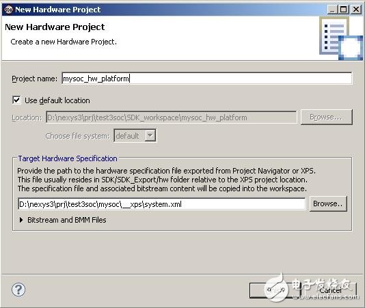
Figure 16 Hardware Platform Configuration Page The next configuration page is shown in Figure 17. Here, set the Project name of the software project and select Select Project Template as "Empty Application". The rest of the options use the default to complete the setup.
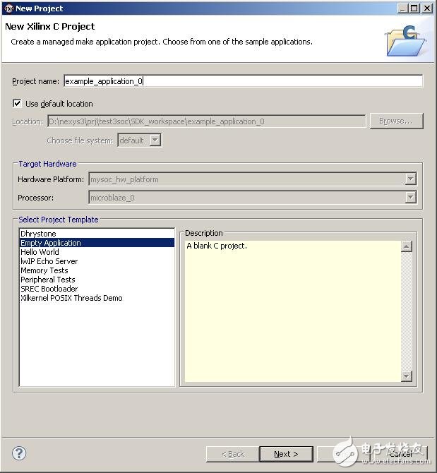
Figure 17 Software Engineering Configuration Page At this point, there are three folders mysoc_hw_platform, empty_application_bsp_0 and example_application_0 under Project Explorer. Right-click on example_application_0 and select Newà Source file to create a new source file called main.c, as shown in Figure 18.
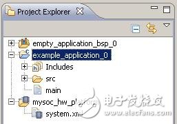
Figure 18 Software Engineering Folder Write a simple water light test code in main.c as follows: /* ------------------------ ------------------------------------ *//* Include File Definitions *//* --- -------------------------------------------------- ------- *///#include "xil_types.h" //This file contains basic types for Xilinx software IP.#include "xparameters.h" //The hardware configuration describes constants#include "xgpio_l.h " //This header file contains identifiers and driver functions #define uchar unsigned char#define uint unsigned short /* --------------------------- --------------------------------- *//* delay function *//* ------- -------------------------------------------------- --- */void delay(uint cnt){ uint i,j; for(i=0;i
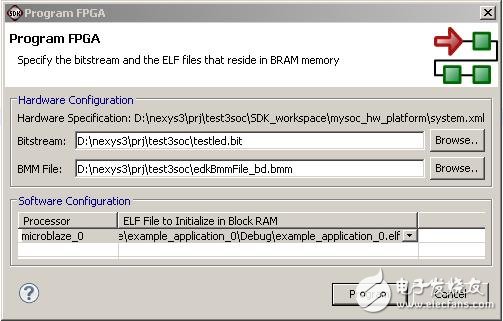 Figure 19 FPGA programming The original Program FPGA is used to burn FPGA devices online, but the current USB connection method of Nexys3 is not directly supported. (This will be studied later. It is said that "white cats and black cats catch mice are good cats", as long as It can be downloaded, but it doesn't matter, we still have Adept. Here, configure some basic information about the file to be burned, and then click on Program, although it will report an error and prompt that it cannot be successfully burned, but at the same time, a download.bit file containing software and hardware burning is generated in the mysoc_hw_platform folder, and finally We use Adept to download this file into Nexys3 to get the running lights online. Reprinted from: privileged classmate's blog
Automotive Wire Harness
Our wire harnesses are widely used for various parts of automobiles and truck , Like engine valve cover gasket/diesel gasket(DORMAN-FORD), headlamp(GROTE), Intelligent Anti-collision System(Mobileye), audio, rearview mirror, power seat, etc. Also the complete engine cable assembies for electric vehicle.
Related Products:ul wiring assembly,engine gasket cable,cable harness.
Automotive Wire Harness,Auto cable assemblies,OEM Automotive Wire Harness
ETOP WIREHARNESS LIMITED , https://www.oemmoldedcables.com