MAX2388 RF front-end chip for 2.3GHz RF and 220MHz IF WCS applications
Abstract: The MAX2388 RF front-end chip integrates an LNA and a mixer. Coupled with an appropriate matching circuit, this chip can be used in the WCS band. In this note, 2.3GHz RF frequency and 220MHz IF are used. Traditional receiver index measurement methods such as gain, noise figure, IIP3, IIP2 and local oscillator leakage are performed on the chip.
MAX2388 is a member of the family of receiver front-end devices (including MAX2387 and MAX2389). These devices integrate a low-noise amplifier and a high linearity direct down-conversion mixer in an ultra-small package, which can simultaneously ensure a very low noise figure. The MAX2387 and MAX2388 also have on-chip LO buffers. The MAX2389 omits this local oscillator buffer to reduce current consumption.
The MAX2387 and MAX2388 are specifically designed for optimal mixing performance, and the local oscillator is driven to -10dBm. The performance of the MAX2389 mixer is optimized to have -4dBm typical drive on the local oscillator input port. An external bias resistor controls the trade-off between the third-order nonlinearity of the mixer and the current consumption.
All devices have high gain and low gain LNA. The MAX2387 has a 32dB gain step, while the MAX2388 and MAX2389 have an 18dB gain step. At the same time, it also has a shutdown mode, the chip can turn off the power during the idle period, thus extending battery life.
Although these receivers were originally designed for the 2110MHz to 2170MHz WCDMA frequency band, they also showed excellent performance in other frequency bands.
The following is the test data on the standard MAX2388 evaluation board. The LNA input and output are retuned to a center frequency of 2315MHz. The mixer matching circuit is tuned to RF input 2315MHz, intermediate frequency output 220MHz and low-end LO injection.
Test Conditions:
Table 1. LNA measurement results
| Parameter | High Gain | Low Gain | Units |
| Gain | 14.0 | 3.7 | dB |
| NF | 2.35 | 7.5 | dB |
| IIP3 | 5.8 | 3.5 | dBm |
| S11 | -12.5 | -4.8 | dB |
| S22 | -15.8 | -7.0 | dB |
| S12 | -24.9 | -13.5 | dB |
| ICC | 10.5 | 7.3 | mA |
Table 2. Mixer measurement results
| Parameter | High Gain | Low Gain | Units |
| Gain | 7.5 | 7.3 | dB |
| NF | 8.5 | 7.5 | dB |
| IIP3 | 5.5 | 0.0 | dBm |
| IIP2 (Note 1) | 27 | 26.5 | dBm |
| LO leakage at IF port | -17.4 | -20.9 | dBm |
| LO leakage at LNA input port | -49.7 | -53.9 | dBm |
Note 1: IIP2 is measured using the half-IF method. The frequency of interference using this method is 2205MHz.
LNA S parameters
The S parameters of the LNA are measured on the MAX2388 evaluation board. Use the port expansion function of the network analyzer to correct the wiring length from the SMA connector to the chip pins. 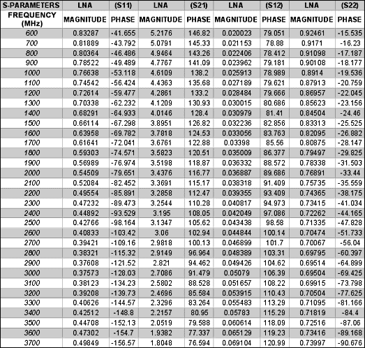
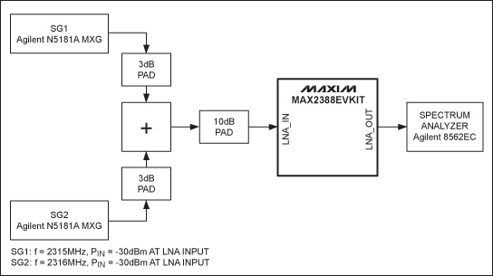
Figure 1. MAX2388 LNA IIP3 test chart 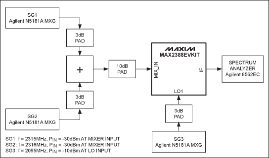
Figure 2. MAX2388 mixer IIP3 test chart 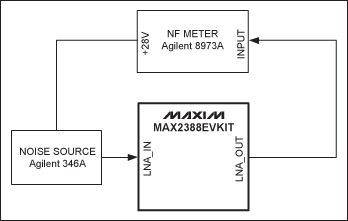
Figure 3. MAX2388 LNA noise figure (NF) test chart 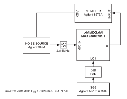
Figure 4. MAX2388 mixer noise figure (NF) test chart
1.0mm Wire To Board Connectors
ShenZhen Antenk Electronics Co,Ltd , https://www.atkconnectors.com