introduction
In recent years, the number of touch phones has increased in geometric multiples, and users can directly interact with the phone system with their fingers. There are basically two ways of touch screen touch: stylus touch and finger touch.
Stylus touch is to use a special touch pen to click on the graphical target on the interface to complete the interaction. This interaction method requires the user to fix the mobile phone device with one hand and the touch pen to touch the touch screen with the other hand. The interaction process requires two hands to participate To complete. Since mobile phone users are often in a mobile state, it is difficult to meet the above operation requirements, and the control efficiency is low. Finger touch can use one hand to hold the hand-held machine, and use the thumb to click or slide to complete the touch control, which is the mainstream of the development of touch screens today.
1 Composition and principle of touch screen
Touch screen technologies suitable for mobile devices and consumer electronics include resistive touch screens and projected capaciTIve touch screens. The touch screen is attached to the surface of the display and used in conjunction with the display to measure the coordinate position of the touch point on the screen, and the intention of the toucher can be known according to the display content or icon of the corresponding coordinate point on the display screen.
1.1 Resistive touch screen
The resistive touch screen is a four-layer transparent composite film screen. At the bottom is a base layer made of glass or plexiglass. At the top is a plastic layer with a hardened outer surface that is smooth and scratch-resistant. In the middle are two conductive metal layers ITO ( Indium TIn Oxide, indium tin oxide, a transparent conductive material), respectively in the base layer and the plastic layer, there are many small transparent isolation points between the two conductive layers to separate them. The structure of the resistive touch screen is shown in Figure 1.
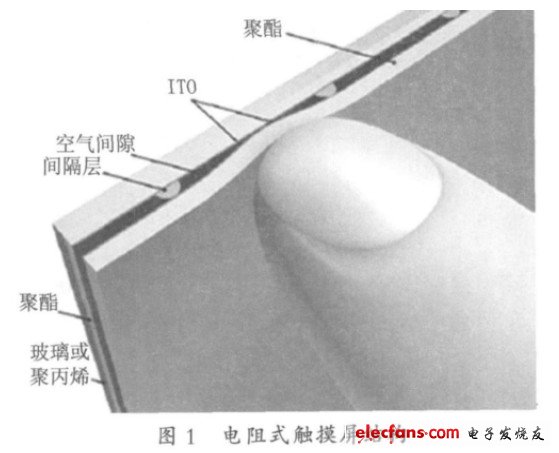
When a finger touches the screen, the two conductive layers are in contact at the touch point. The two metal conductive layers of the touch screen are the two working surfaces of the touch screen, and a silver glue is coated on each end of each working surface, which is called a pair of electrodes on the working surface. If a voltage is applied to an electrode pair on a working surface, a uniform and continuous parallel voltage distribution will be formed on the working surface. When a certain voltage is applied to the electrode pair in the X direction and no voltage is applied to the electrode pair in the Y direction, in the X parallel voltage field, the voltage value at the contact point can be reflected on the Y + (or Y-) electrode The X coordinate value of the contact can be obtained by measuring the voltage of the Y + electrode to ground. Similarly, when voltage is applied to the Y electrode pair and no voltage is applied to the X electrode pair, the Y coordinate of the contact can be obtained by measuring the voltage of the X + electrode, as shown in Figure 2. According to the X coordinate and Y coordinate, the position of the touch point on the screen can be known.
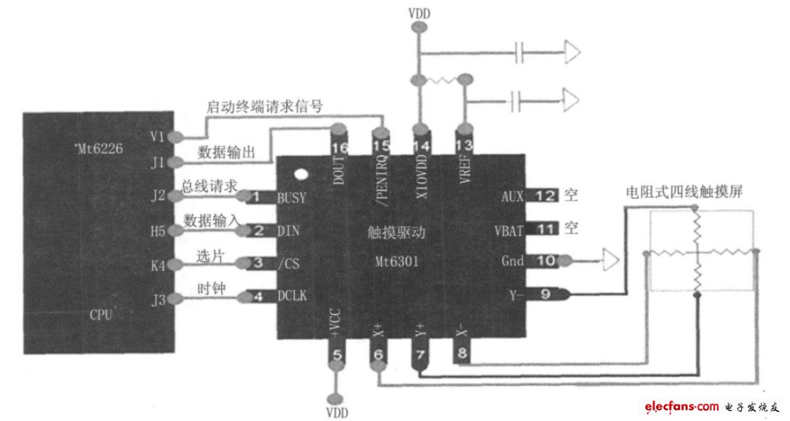
Figure 2 Circuit diagram of resistive touch screen
Resistive touch screen is a large-volume application and low-cost technology. Its disadvantages are: thick stack, relatively complicated; poor optical performance, requiring high-power backlight; can not detect the action of multiple fingers; must be under pressure to act; need User calibration.
1.2 Projected capacitive touch screen
There are two main types of projected capacitive touch technology: one is self-capacitance and the other is mutual capacitance.
Mutual capacitance screens are also made of ITO with horizontal electrodes and vertical electrodes on the glass surface, where two sets of electrodes intersect will form a capacitor, that is, these two sets of electrodes respectively form the two poles of the capacitor, forming a capacitor matrix.
As shown in Figure 3, when the finger touches the capacitive screen, since the human body is conductive, a new capacitance is formed between the ITO electrode and the finger, thereby changing the capacitance between the original two ITO electrodes. When detecting the mutual capacitance between the two electrodes, the horizontal electrodes sequentially emit excitation signals, and all the vertical electrodes receive the signals at the same time. In this way, the capacitance value at the intersection of all horizontal and vertical electrodes can be obtained, that is, the capacitance of the entire two-dimensional plane of the touch screen.
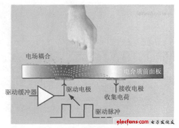
Figure 3 Projected capacitive touch screen
According to the two-dimensional capacitance change data of the touch screen, the intersection with the strongest row and column sensor signals is the touch point. As shown in Figure 4, the numerical approximation by interpolation can determine the coordinate value of the finger position very accurately. The purpose of designing a projected capacitive sensor array is to enable fingers to interact with more than one X sensor and more than one Y sensor at the same time, and combine with other technologies to achieve multi-touch.
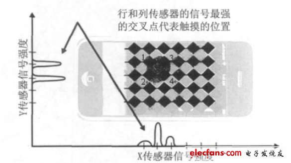
Figure 4 The signal strength of the row and column sensors determines the location of the touch
When several touch buttons are close to each other, the approaching finger will cause the capacitance of multiple buttons to change. Atmel's patented Adjacent Key Suppression (AKS) technology uses an iterative method to repeatedly measure the change in capacitance on each key, and compare the results to determine which key is the user's desire. AKS suppresses or ignores signals from all other keys and provides signals of selected keys, which prevents false touches of adjacent keys.
The advantages of the projected capacitive touch screen compared to other touch screen technologies are: high signal-to-noise ratio; the clarity and brightness of the touch screen surface is higher than that of the resistive screen; it can support multi-touch; no user calibration is required. One of its shortcomings is that there is no response when wearing gloves or touching with an insulator. In addition, there is a drift phenomenon, which will be insensitive when the temperature or humidity is high, and will malfunction when the human body or the other hand is close.
Category 8, or just Cat8, is the latest standard in copper Ethernet Cable. It represents a significant leap in data transfer speed over the earlier Cat7 and Cat6a network cables. It uses standard RJ45 connectors and is backwards compatible with previous standards.
Cat8 is the fastest Ethernet cable yet. It's data transfer speed of up to 40 Gbps is four times faster than Cat6a, while its support of bandwidth up to 2 GHz (four times more than standard Cat6a bandwidth) reduces latency for superior signal quality.

Cat 8 Cable,Cat8 Ethernet Cable,Cat8 Indoor Ethernet Cable,High Speed Cat8 Cable
Shenzhen Kingwire Electronics Co., Ltd. , https://www.kingwires.com