As shown in the figure, a three-way switch conversion circuit diagram consisting of a six-inverting buffer three-state output CD4052 and a four-input NAND gate CD4011 (A1 to A3) is mainly used in the sound source switching of the stereo sound system.
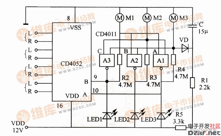
Switching circuit
The circuit diagram uses touch control and has three input channels M1 to M3. The three gates A1 to A3 and the output terminals of the NAND gate CD4011 are connected to the external address inputs A and B of the CD4052, and form a three-way touch interlock switch controller with other related components.
When the circuit is in a steady state, there is always one gate of A1~A3 whose output is low, and the output of the other two gates must be high. The low level of the output passes through the input terminals of the two gates of the resistors R2 to R4, so that it outputs a high level after being inverted, forming an interlocking relationship. When the A and B input terminals of the CD4052 are in different states, the channel corresponding to the address code is turned on, thereby achieving the purpose of switching.
Z10 Bone Conduction Earphone,Wireless Bluetooth Air Conduction Headphone,Wireless Headset Bone Conduction,Wireless Bluetooth Headphone
Shenzhen Lonfine Innovation Technology Co., Ltd , https://www.lonfinesmart.com