Because the functions of each type of inverter are different, and the names of the same function parameters are also inconsistent, for the convenience of description, this paper takes the basic parameter name of the inverter as an example. Since the basic parameters are almost all types of frequency converters, it is completely possible to bypass the class.
One acceleration and deceleration time
The acceleration time is the time required for the output frequency to rise from 0 to the maximum frequency, and the deceleration time is the time required to fall from the maximum frequency to 0. Usually taken from: the industrial transformer uses the frequency setting signal to rise and fall to determine the acceleration and deceleration time. When the motor is accelerating, the rate of increase of the frequency setting must be limited to prevent overcurrent, and when decelerating, the rate of decrease is limited to prevent overvoltage.
Acceleration time setting requirement: Limit the acceleration current below the overcurrent capacity of the inverter, and do not cause the inverter to trip due to the over-speed. The deceleration time setting point is: prevent the smoothing circuit voltage from being too large, and do not make the regenerative overvoltage stall. Let the frequency converter trip. Acceleration and deceleration time can be calculated according to the load, but in the debugging, it is often set to set the long acceleration/deceleration time according to the load and experience. Observe the overcurrent and overvoltage alarm by starting and stopping the motor; then gradually set the acceleration/deceleration time. Shorten, the principle of no alarm occurs during operation, and repeat the operation several times to determine the optimal acceleration and deceleration time. Inverter basic parameter setting and debugging
Two torque boost
Also called torque compensation, it is a method to increase the low frequency range f/V to compensate for the torque reduction at low speed caused by the resistance of the stator winding of the motor. When set to automatic, the voltage during acceleration can be automatically increased to compensate for the starting torque, so that the motor accelerates smoothly. If manual compensation is used, a better curve can be selected by experiment depending on the load characteristics, especially the starting characteristics of the load. For variable torque loads, if the selection is improper, the output voltage will be too high at low speed, and the phenomenon of wasting electric energy may even occur when the motor is loaded with load and the current is large, and the speed is not going up.
Three-electron thermal overload protection
This function is set to protect the motor from overheating. It is the CPU inside the inverter calculates the temperature rise of the motor according to the running current value and frequency, thus performing overheat protection. This function is only applicable to the “one-for-one†occasion, and in the case of “one-to-oneâ€, a thermal relay should be added to each motor.
Electronic thermal protection set value (%) = [motor rated current (A) / inverter rated output current (A)] × 100%.
Four frequency limit
That is, the upper and lower limits of the inverter output frequency. The frequency limit is a protection function that prevents the device from malfunctioning or the external frequency setting signal source is faulty, causing the output frequency to be too high or too low to prevent damage to the device. In the application, it can be set according to the actual situation. This function can also be used for speed limit. If there are some belt conveyors, because there is not much material to be transported, in order to reduce the wear of machinery and belts, the inverter can be driven and the upper limit frequency of the inverter can be set to a certain frequency value. This allows the belt conveyor to operate at a fixed, low working speed.
Five offset frequency
Some are also called deviation frequency or frequency deviation setting. Its purpose is to use the function to adjust the output frequency of the lowest frequency setting signal when the frequency is set by the external analog signal (voltage or current). Some inverters have the deviation value when the frequency setting signal is 0%. It can be used in the range of 0~fmax. Some inverters (such as Mingdianshe and Sanhao) can also set the bias polarity. For example, when the frequency setting signal is 0% during debugging, the inverter output frequency is not 0Hz, but is xHz. At this time, the offset frequency is set to negative xHz to make the inverter output frequency 0Hz.
Six frequency setting signal gain
This function is only effective when the frequency is set with an external analog signal. It is used to compensate for the inconsistency between the external set signal voltage and the internal voltage of the inverter (+10v); at the same time, it is convenient to select the analog set signal voltage. When setting, when the analog input signal is maximum (such as 10v, 5v or 20mA), find the frequency percentage of the f/V pattern that can be output and set it as a parameter; if the external setting signal is 0~5v, if the output frequency of the inverter is 0~50Hz, the gain signal will be Set to 200%.
Seven torque limit
It can be divided into two types: drive torque limit and brake torque limit. It is based on the output voltage and current value of the inverter, and the torque calculation is performed by the CPU, which can significantly improve the shock load recovery characteristics during acceleration and deceleration and constant speed operation. The torque limit function enables automatic acceleration and deceleration control. It is assumed that the acceleration/deceleration time is less than the load inertia time, and the motor can be automatically accelerated and decelerated according to the torque set value.
The drive torque function provides a powerful starting torque. During steady-state operation, the torque function will control the motor slip and limit the motor torque to the maximum set value. When the load torque suddenly increases, even When the acceleration time is set too short, it will not cause the inverter to trip. When the acceleration time setting is too short, the motor torque will not exceed the maximum set value. A large driving torque is advantageous for starting, and it is preferable to set it to 80 to 100%.
The smaller the brake torque setting value is, the larger the braking force is. It is suitable for the occasion of sudden acceleration and deceleration. If the brake torque setting value is set too high, an overvoltage alarm phenomenon will occur. If the braking torque is set to 0%, the total amount of regeneration applied to the main capacitor can be close to zero, so that when the motor is decelerating, it can be decelerated to stop without tripping without using the braking resistor. However, in some loads, if the braking torque is set to 0%, a short idling phenomenon will occur during deceleration, causing the inverter to start repeatedly, the current fluctuates greatly, and the inverter will trip if it is serious, which should be noticed. Setting and debugging of this parameter of the inverter
Â
Eight plus deceleration mode selection
Also called acceleration and deceleration curve selection. Generally, the inverter has three kinds of curves: linear, nonlinear and S. Usually, most of the linear curves are selected; the nonlinear curve is suitable for variable torque loads, such as fans; the S curve is suitable for constant torque loads, and the acceleration and deceleration changes are relatively slow. According to the load torque characteristics, the corresponding curve can be selected according to the load torque characteristics. However, when debugging the inverter of a boiler induced draft fan, the nonlinear curve is selected for the acceleration/deceleration curve, and the inverter is tripped and adjusted together. Changing many parameters has no effect, and then it is normal after changing to the S curve. The reason is: before starting, the induced draft fan rotates by itself due to the flue gas flow, and reverses to become a negative load. Thus, the S curve is selected, so that the frequency of the initial start is slower, thus avoiding the inverter. The occurrence of a trip, of course, is the method used for a frequency converter that does not have a DC braking function.
Nine torque vector control
Vector control is based on the theory that asynchronous motors have the same torque generation mechanism as DC motors. The vector control method is to decompose the stator current into predetermined magnetic field currents and torque currents, and separately control the stator currents to be output to the motor. Therefore, the same control performance as the DC motor can be obtained in principle. With the torque vector control function, the motor can output the maximum torque under various operating conditions, especially the motor running in the low speed range.
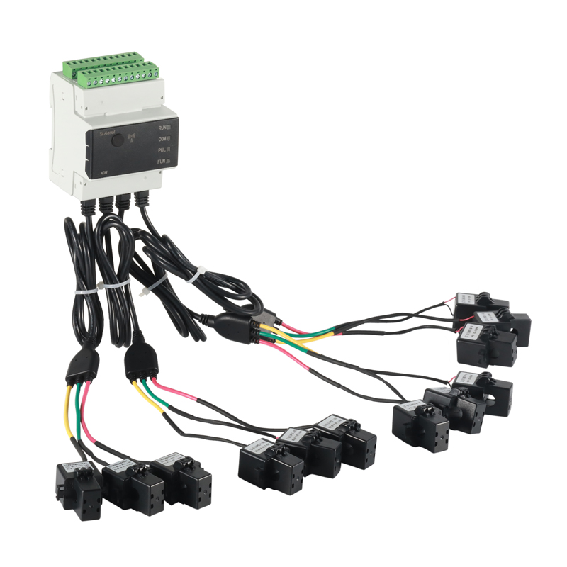
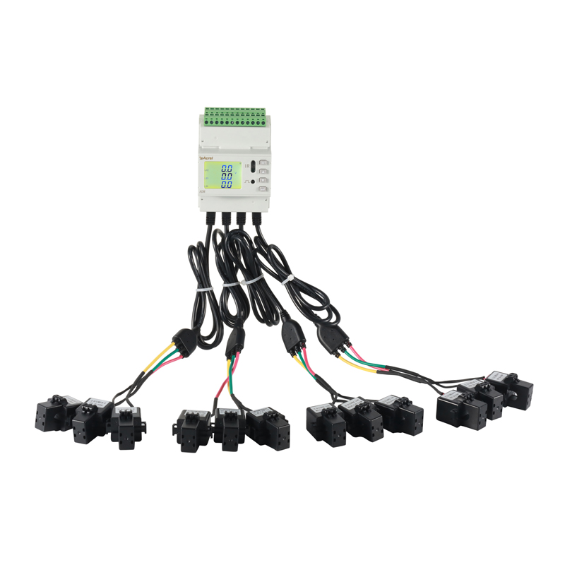
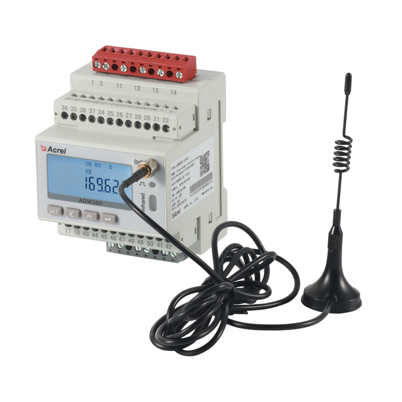
The power Internet of Things combines various electrical measurement, metering, non-electrical measurement, protection and other instruments and equipment in the traditional power industry with the current popular Internet of Things technology, breaking the traditional networking, debugging, and application methods, making it more convenient for users to use related platforms. Intuitively see the comprehensive information of the target site. ADW series has ADW200, ADW300 two types of IoT power meter, corresponding to various industrial applications.
ADW200 rail type multi circuit IoT Energy Meter is mainly used for various three-phase power parameter measurement and active and reactive power measurement of low-voltage networks. At the same time, the current input of up to four circuits can be selected. three phase wifi energy meter has RS485 communication and 470MHz wireless communication functions. A variety of expansion modules are available to facilitate users to monitor, collect and manage electricity consumption. wireless smart energy meter can be flexibly installed in the distribution box to realize sub-item electric energy measurement, statistics and analysis for different areas and different loads.
ADW300 wireless energy meter is mainly used for the measurement of various electrical parameters of medium and low voltage networks and the measurement of active and reactive power. smart iot energy meter has RS485 communication and a variety of wireless communication options, which is convenient for users to monitor, collect and manage electricity consumption. lora energy meter can be flexibly installed in the distribution box to realize sub-item electric energy measurement, statistics and analysis for different areas and different loads.


three phase wifi energy meter,wireless smart energy meter,wireless energy meter,smart iot energy meter,lora energy meter
Jiangsu Acrel Electrical Manufacturing Co., LTD. , https://www.acrel.com.pk