Abstract: Due to the limited size and weight of the power supply used in the instrument, a switching power supply design method controlled by a MOSFET and isolated by a high frequency transformer is proposed. The power source has the characteristics of small volume, light weight, strong anti-interference performance, stable output voltage, wide voltage regulation range, fast voltage dynamic response, high cost performance and convenient use.
introductionThe power FET MOSFET is a unipolar voltage control device. It not only has self-shutdown capability, but also has the advantages of small driving power and fast turn-off speed. It is a commonly used switching device in switching power supplies. The MOSFET-controlled switching power supply has the advantages of small size, light weight, high efficiency, and low cost, so it is more suitable for instrument power supply. This paper presents a large-scale continuously adjustable (0 ~ 45V) small power regulated power supply design example controlled by MOSFET.
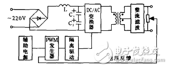
First, the overall structure and the main circuitFigure 1 is a block diagram showing the overall structure of the power supply. The working principle is as follows:

Figure 1 schematic block diagram
The full-bridge rectifier circuit rectifies the grid voltage of 220V into an unadjustable DC voltage Ud=1.2U, which is approximately equal to 198V. The voltages on the two equal-valued filter capacitors are respectively above 99V. After being inverted by the DC/AC converter, the output is 20kHz, the AC voltage with adjustable pulse width, and the two secondary sides of the high-frequency transformer are sent in positive and negative half cycles. The rectification and filtering circuit outputs a DC voltage. The magnitude of the DC output voltage of the power supply is controlled by the output pulse width of the PWM generator.
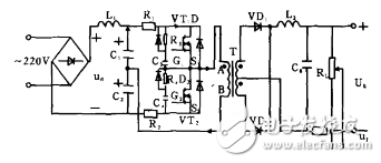
The main circuit is shown in Figure 2.

Figure 2 main circuit
The key components for implementing the DCPAC conversion in the main circuit are the power FETs VT1 and VT2. When the VT1 tube is turned on and the VT2 is turned off, the current in the circuit flows from the positive terminal of the capacitor C1 to the D1-S1 of the VT1, and then returns to the negative pole of the capacitor C1 through the primary side of the transformer to form a loop, and uAB is a positive voltage. The secondary side induced voltage of the transformer is positive at the same name, VD1 is turned on, and the output U0 is positive and negative.
When VT2 is turned on and VT1 is turned off, the above conclusion can also be drawn: U0 is positive and negative. The size of U0 depends on the conduction time of the control circuit to make VT1 and VT2.
Second, the control circuitThe control circuit function is to realize the PWM waveform synthesis and the isolated drive of the controllable DC/AC converter.
1, the generation of PWM waveformThe power supply design of this circuit is a +-15V DC regulated power supply with a three-terminal integrated voltage regulator as the core.
(1) PWM control principle
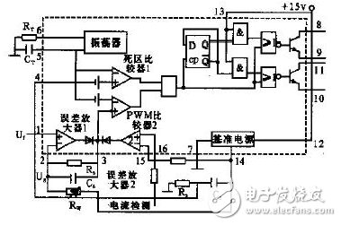
Pulse width PWM waveform generation uses a powerful TL494 fixed-frequency modulation chip, the chip has 16 pins, the internal circuit and peripheral circuit shown in Figure 3.

Figure 3 TL494 internal circuit and peripheral circuits
Focusing on the development and production of Wireless Charging products that make life easier.
Supply various wireless charger including multifunctional Wireless Charger, Car Wireless Charger, Magnetic Wireless Chargin, Wireless Charging Mouse Pad, etc.
We help 200+ customers create custom wireless charging products design for various industries.
Manufacturing high quality products for customers according to international standards, such as CE ROHS FCC REACH UL SGS BQB etc.
Wireless Charging Pad,Wireless Phone Charger,Wireless Car Charger,Bluetooth Charger
TOPNOTCH INTERNATIONAL GROUP LIMITED , https://www.mic11.com