JTAG (JointTestAcTIonGroup, Joint Test Action Group) is an international standard test protocol, mainly used for internal chip testing and simulation and debugging of the system. JTAG technology is an embedded debugging technology, which encapsulates special tests inside the chip. The circuit TAP (TestAccessPort, test access port), through the dedicated JTAG test tool to test the internal nodes.
Most of today's more complex devices support JTAG protocols such as ARM, DSP, and FPGA devices. The standard JTAG interface is 4-wire: TMS, TCK, TDI, TDO for test mode selection, test clock, test data input, and test data output. There are two standards for the JTAG interface connection today, the 14-pin interface and the 20-pin interface, which are defined as follows.
14-pin JTAG interface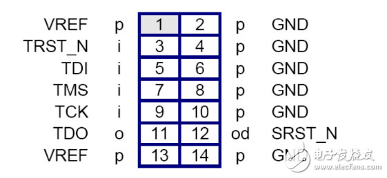
1, 13 VCC power supply
2, 4, 6, 8, 10, 14 GND ground
3 nTRST test system reset signal
5 TDI test data serial input
7 TMS test mode selection
9 TCK test clock
11 TDO test data serial output
12 NC not connected
20-pin JTAG interface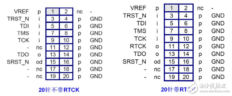
1 VTref target board reference voltage, connected to the power supply
2VCC power supply
3nTRST test system reset signal
4, 6, 8, 10, 12, 14, 16, 18, 20 GND Ground
5TDI test data serial input
7TMS test mode selection
9TCK test clock
11RTCK test clock return signal
13TDO test data serial output
15nRESET target system reset signal
17, 19NC is not connected
10-pin JTAG interface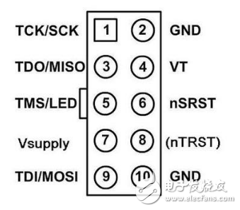
Emulator port AVR port note
1.TCKTCK
2.NCNC
3.TDOTDO
4.VtrefVCC
5.TMSTMS
6.nSRSTRESET
7.NC/VsupplyNC/VCCJTAGICE Simulator: VCC; JTAGICEmkII Simulator: NC
8.nTRSTNCATMEL still keeps the port, but it is not used now, it may be used in the future.
9.TDITDI
10.GNDGND
Air Handing System,Air Handing Unit System,Air Ventilation System,Air Heating Cooling System
Chongqing LDJM Engine Parts Center , https://www.ckcummins.com