Transistor switching circuits (operating in a saturated state) are common in modern circuit design applications. The classic 74LS, 74ALS and other integrated circuits use transistor switching circuits inside, but the driving capability is general. The TTL transistor switching circuit is divided into a small signal switching circuit and a power switching circuit according to the driving capability; according to the transistor connection mode, the emitter grounding (PNP transistor emitter is connected to the power source) and the emitter level following switching circuit are divided. 1. Emitter grounding switch circuit 1.1NPN type and PNP type basic switch schematic: 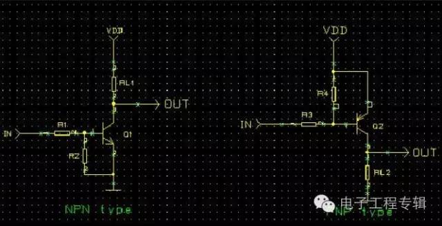
The above basic circuit is still some distance from the actual design circuit: due to the accumulation effect of the transistor base charge storage, there is a transition process from on to off (when the transistor is turned off, the base charge is slowed down due to the presence of R1). The release, so Ic will not immediately become zero). That is to say, the emitter grounding type switching circuit has a turn-off time and cannot be directly applied to the medium and high frequency switches. 1.2 Practical NPN type and PNP type switching principle Figure 1 (adding accelerating capacitor) 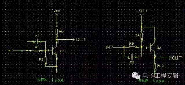
Explanation: When the transistor is suddenly turned on (the IN signal suddenly jumps), C1 is short-circuited instantaneously, providing a fast base current for the transistor, which accelerates the conduction of the transistor. When the transistor is suddenly turned off (the IN signal suddenly jumps), C1 is also turned on instantaneously, providing a low-impedance path for discharging the base charge, which speeds up the turn-off of the transistor. C usually takes tens to hundreds of picofarads. R2 in the circuit is to ensure that the triode remains off when there is no IN input high level; R4 is to ensure that the triode remains off when there is no IN input low. R1 and R3 are used for base current limiting. 1.3 Practical NPN Switching Principle Figure 2 (V-Diode Diode Clamp) 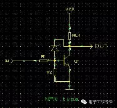
Explanation: Since the Vt diode Vf is 0.2 to 0.4V smaller than Vbe, when the transistor is turned on, most of the base current flows from the diode and then through the transistor to the ground, so the current flowing to the base of the transistor is small. The accumulated charge is also small. When the transistor is turned off (the IN signal suddenly jumps), the amount of charge that needs to be discharged is small, and the shutdown is naturally fast. 1.4 actual circuit design In the actual circuit design, it is necessary to consider the triode Vceo, Vcbo, etc. to meet the withstand voltage, the triode meets the collector power consumption; calculate the base resistance (calculated as the base current) by the load current and hfe (calculated by the minimum hfe of the triode) Leave a margin of 0.5 to 1 times). Pay attention to the reverse withstand voltage of the special diode. Triode Switch Circuit Design The triode can be used as a switch in addition to an AC signal amplifier. Strictly speaking, the triode is not exactly the same as the general mechanical contact switch, but it has some features that are not found in mechanical switches. Figure 1 shows the basic circuit diagram of the triode electronic switch. As can be seen from the figure below, the load resistor is directly connected between the collector of the triode and the power supply, and is located on the loop of the main current of the triode. 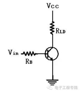 Figure 1 The basic triode switch input voltage Vin controls the open (closed) and closed (closed) action of the triode switch. When the triode is open, the load current is blocked. Conversely, when the triode is closed, the current is Can be circulated. In detail, when Vin is low voltage, since there is no current at the base, there is no current in the collector, so that the load connected to the collector terminal has no current, which is equivalent to the opening of the switch. At this time, the triode is superior to Cutoff area. Similarly, when Vin is at a high voltage, since the base current flows, the collector flows through a larger amplification current, so the load circuit is turned on, which is equivalent to the closing of the switch, and the triode is superior. In the saturation zone (saturation). 838 Electronics
The analysis design of the triode switching circuit is based on the fact that the forward bias voltage of the base emitter junction is about 0.6 volts for the silicon triode. Therefore, in order to turn off the triode, Vin must be lower than 0.6 volt to make the base of the triode. The pole current is zero. Usually at the time of design, in order to be more certain that the triode must be in the off state, the Vin value is often less than 0.3 volts. (838 electronic resources) Of course, the closer the input voltage is to zero volts, the more the transistor switch will be in the off state. To deliver current to the load, the collector and emitter of the transistor must be shorted, just like the closing action of a mechanical switch. In order to achieve this, Vin must reach a high enough level to drive the triode into the saturation working area. When the triode is saturated, the collector current is quite large, almost making the entire power supply voltage Vcc across the load resistance. Then VcE is close to 0, and the collector and emitter of the transistor are almost short-circuited. Under ideal conditions, according to the Ohm's law, the collector current should be:  Therefore, the base current should be at least:
The above equation shows the basic relationship between IC and IB. The β value in the equation represents the DC current gain of the triode. For some triodes, there is a big difference between the AC β value and the DC β value. To make the switch closed, its Vin value must be high enough to deliver a minimum base current value that is greater than or equal to that required by Equation 1. Since the base circuit is only a series circuit of a resistor and a base emitter junction, Vin can be solved by: 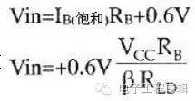
Equation 2) Once the base voltage exceeds or is equal to the value obtained by Equation (2), the transistor is turned on, so that all of the supply voltage is across the load resistor, and the closing action of the switch is completed. In summary, after the triode is connected to the circuit of Figure 1, its function is the same as a mechanical switch connected in series with the load, and its way of opening and closing the switch can be directly controlled by the input voltage without using Mechanical actuators commonly used in mechanical switches, such as mechanical actuators, solenoid plungers, or relay armatures. In order to avoid confusion, the triode switches described in this article use NPN transistors. Of course, NPN transistors can also be used as switches, but they are less common. Example 1 tries to explain the input voltage required to make the switch closed (triode saturation) in the switching circuit of Figure 2. And explain the load current and base current value at this time? Solution: It can be seen from Equation 2 that in the saturated state, all the supply voltages fall across the load resistance completely, so it is known from equation (1)


Therefore, the input voltage can be obtained by: 
Figure 2 uses a triode as a light bulb switch 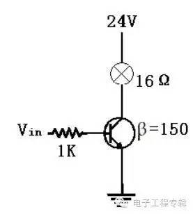
According to the example 1-1, it is only necessary to use a small control voltage and current to control the opening and closing action of the load current up to 1.5A by using the triode switch. In addition, although the triode flows a large current, it does not need to be equipped with a heat sink, because when the load current flows, the triode is saturated, and its VCE approaches zero, so the power multiplied by the current and voltage is very small. No heat sink is required.
Comparison of Transistor Switch and Mechanical Switch So far, we have assumed that when the triode switch is turned on, its base and emitter are completely short-circuited. This is not the case. No triode can be completely shorted and VCE=0. Most small-signal silicon transistors have a VCE (saturation) value of about 0.2 volts when saturated, even though they are designed for switching applications. Its VCE (saturation) value can only be as low as about 0.1 volts, and the load current is high, and the VCE (saturation) value will rise slightly, although for most analytical calculations, VCE (saturation) The value can be ignored, but when testing the switching circuit, it must be understood that the VCE (saturation) value is not really zero. Although the voltage of VCE (saturated) is very small, it is insignificant in itself. However, if several triode switches are connected in series, the sum of the voltage drop effects is considerable. Unfortunately, mechanical switches are often connected in series. Working, as shown in Fig. 3(a), the triode switch cannot simulate the equivalent circuit of the mechanical switch (as shown in Fig. 3(b)), which is a major disadvantage of the triode switch. 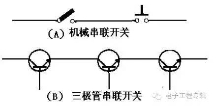
Figure 3 Transistor Switch and Mechanical Switch Circuit Fortunately, the triode switch is not suitable for the serial connection method, but it can be perfectly applied to the parallel connection mode. As shown in Figure 4, it is an example. Compared with traditional mechanical switches, triode switches have the following four advantages: 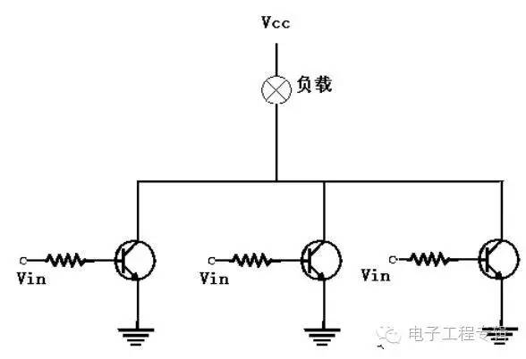
Figure 4: Parallel connection of triode switch (1) Transistor switch does not have active contact part, so there is no wear and tear, it can be used infinitely many times, general mechanical switch, due to contact wear, only use millions at most The second time, and its contacts are susceptible to fouling and affect the work, so it can not operate in a dirty environment, the triode switch is neither contact nor sealed, so there is no such concern.
(2) The operating speed of the triode switch is faster than that of the general switch. The opening and closing time of the general switch is calculated in milliseconds (ms), and the triode switch is measured in microseconds (μs).
(3) The triode switch has no bounce phenomenon. The general mechanical switch will have a fast continuous opening and closing action at the moment of conduction, and then gradually reach a steady state.
(4) When a triode switch is used to drive an inductive load, no spark is generated at the moment the switch is turned on. Conversely, when the mechanical switch is turned on, since the current on the inductive load is cut off instantaneously, the instantaneous induced voltage of the inductor will cause an arc at the contact. This arc will not only erode the surface of the contact, but may also cause interference or harm.
Motion Control Sensor is an original part that converts the change of non-electricity (such as speed, pressure) into electric quantity. According to the converted non-electricity, it can be divided into pressure sensor, speed sensor, temperature sensor, etc. It is a measurement, control instrument and Parts and accessories of equipment.
Absolute Rotary Encoder,Absolute Linear Encoder,Absolute Optical Encoder,Absolute Position Encoder
Changchun Guangxing Sensing Technology Co.LTD , https://www.gx-encoder.com