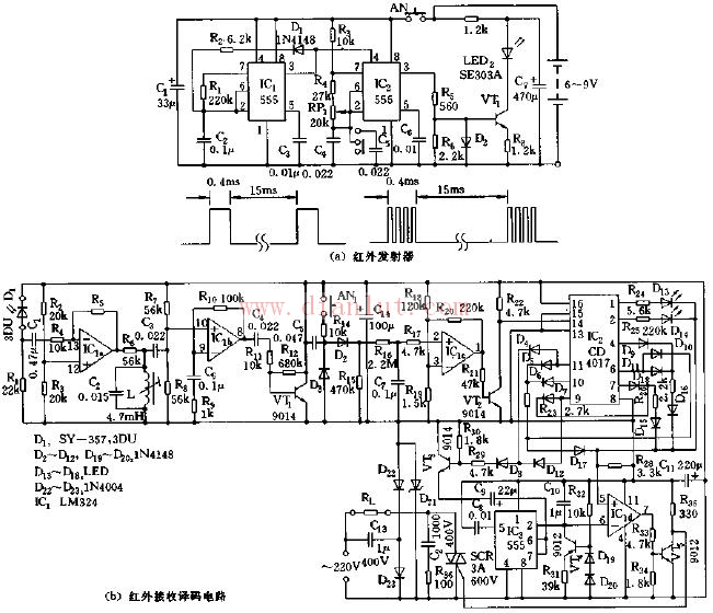
As shown in the figure, the infrared remote control fan speed switch circuit. The circuit consists of an infrared emitter and an infrared receiver and decoder. The infrared emitter includes a low frequency multivibrator composed of IC1 and D1, R1, R2, C2, and the like, and a multivibrator composed of IC2 and R3, R4, C4, C5, W1, and the like. The oscillation period corresponding to IC1 is T=tcharge+t, and tcharge=0.693R2C2, the graph parameter corresponds to about 400μs; tput=0.693R1C2, the graphical parameter corresponds to about 15ms, the duty cycle of the output waveform About 3%. There are two kinds of oscillation frequencies corresponding to IC2: f1=1.44/(R3+2R4+2Rw1)(C4), f2=1.44/(R3+2R4+2Rw1)(C4+C5), and the corresponding parameters are f = 20 kHz, f2 = 10 kHz. In addition, the output waveform of IC1 controls the oscillation of IC2, and when the pulse waveform of IC2 is low, the oscillator Ic2 does not operate. The infrared emission tube adopts the SE303A type, and the pulse code modulation waveform is shown in (a). The infrared receiving tube adopts the PH302 matched with the transmitting tube, and the photosensitive transistor of the 3DU type can also be used. The integrated circuit IC1 is a quad op amp LM324, of which IC1a. The L and C2 circuits form a 20 kHz (or 10 kHz) frequency selective amplifier, IC1b and BG1 are amplifiers, and IC1c and R17 to R20 form a voltage comparator. The signal is detected and then added to the inverting input of the voltage comparator after 150ms delay of R16 and C7. Only when the signal voltage exceeds the bias voltage of the non-inverting terminal, the output of IC1c will change from high level to low level. . Therefore, the pressing time (AN) at the time of transmission should be not less than 150 ms. The integrated circuit IC2 adopts the decimal counter/pulse distributor CD4017, and selects 8 output terminals BG1~BG5, BG7~BG9, and internally R25, R27, R26, R23, R24, and is divided with R28 and then applied to the voltage comparator Icld. The same phase. IC3 (555), IC1d, BG4, etc. constitute a multi-vibrator with adjustable duty cycle with constant current source. The magnitude of the duty cycle depends on the level of the bias voltage applied to the non-inverting terminal of IC1d. The output of IC1d triggers the SCR triac after being inverted by BG5, and changes the average value of the AC voltage by controlling the on-time of its trigger, thereby changing the corresponding speed. Corresponding to the output BG1 to BG5 of IC2, the fan has five continuous winds with different wind speeds, and when BG7 to BG9 are output, it corresponds to the third-wind gust and breeze. The transmission of this circuit adopts infrared pulse coding, which can reliably receive and decode the receiving decoders in the range of 5~10m, and can realize 5 different wind speeds (continuous wind) and third-wind gusts and breeze to the fan. Shift control.
PVC Power Cable NYY
Standard: VDE0276, VDE0271, IEC 60502
Rated Voltage: 0.6/1kV
Others: Fire Cable and other property Low Voltage Power Cable can be available
Applications: Those LV Power Cables used for electricity supply in fixed installation, power networks,underground and in cable ducting where where mechanical damages are not to be expected.
Nyy Cables,Nyyj Cable,Nyy Flexible Cable,Nyy Power Cable
Shenzhen Bendakang Cables Holding Co., Ltd , https://www.bdkcables.com