Dimming with a switching regulator
In order to achieve switching hundreds of times per second or even thousands of times, switching regulator-based LED drivers require special design considerations. Regulators designed for standard power supplies typically have a "start" or turn-off pin for logic PWM signals, but the associated delay t D is quite long, due to the design of the silicon chip that emphasizes the response. Maintain low shutdown current for a period of time. However, the switching regulator dedicated to driving the LEDs is just the opposite. It keeps the internal control circuit active when the "start" pin logic is low to minimize tD, and when the LED is turned off, Will face the trouble of large operating current.
When using PWM to achieve light control optimization, keep the Slew-up and Slew-down delays to a minimum, not only to get the best contrast, but also to reduce the LED spend by 0. The time required to reach the goal. (Under this condition, the main wavelength or CCT is not guaranteed to be the same as the target value.) The standard switching regulator here will have a soft start, usually with a soft shutdown, and the dedicated LED driver will be in its control. All work is performed to reduce these slew rates. To reduce t SU and t SD , it is necessary to start with the design of the silicon chip and the topology used by the switching regulator.
The buck regulator with faster slew rate performs better than all other switching topologies in two places. First, the buck regulator is the only switch that delivers power to the output when the control switch is activated. Converter, this feature makes the control loop of a buck regulator for voltage mode or current mode PWM (not to be confused with PWM dimming) faster than a boost regulator or other buck/boost topology. In addition, the power transfer during the start of the control switch can be easily changed to hysteresis control, making it even faster than the optimal voltage mode or current mode controlled loop. Second, the inductor of the buck regulator is connected to the output during the entire switching cycle, which ensures continuity of the output current, which means that no output capacitor is needed. With fewer output capacitors, the buck regulator becomes a true high-impedance current source that can quickly convert the output voltage. While Cuk and Zeta converters offer continuous output inductors, they are not the best choice because of their slower control loops and lower efficiency.
PWM is faster than "start" pin
Even a pure hysteresis buck regulator without an output capacitor is not sufficient for some PWM dimming systems. These applications require higher PWM dimming frequency, high contrast, and faster requirements. Swing rate and a shorter delay time. When used in conjunction with mechanical vision and industrial inspection systems, some systems that require high performance, including liquid crystal (LCD) panels and projector backlighting systems, in some cases, the PWM dimming frequency must be increased to A band of 25 kHz or higher outside the audible band, as the overall dimming period has been shortened to within a few microseconds, including the conduction delay, the sum of the rise and fall times of the LED current must be shortened to within nanoseconds.
Starting with a fast buck regulator without an output capacitor, the delay in the output current turn-on and turn-off is the conduction delay from the integrated circuit itself and the physical characteristics of the output inductor. To achieve true high-speed PWM dimming, both delays must be skipped (By Pass). The best way to achieve this is to use a power switch in parallel with the LED (Figure 3). When the LED is turned off, the drive current is shunted through the switch, acting like a typical N-type metal oxide semiconductor field effect transistor (N-MOSFET), where the integrated circuit will continue to operate and the inductor current will continue to flow. The biggest disadvantage of this method is that when the LED is turned off, power is wasted even if the output voltage drops during the same period as the current sense voltage.
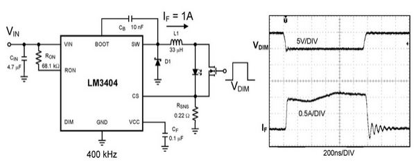
Figure 3 shunt FET circuit and its waveform
Dimming with a shunt field effect transistor (FET) results in a sharp shift in the output voltage, which causes the integrated circuit's control loop to respond in an attempt to maintain output current stability. Just as with logic pin dimming, the faster the control loop, the better the response, and the hysteresis controlled buck regulator provides the best response.
The fresnel lens is a thin sheet made of plastic material. One side of the lens surface is smooth, and the other side is molded with concentric circles from small to large. Its grooves is designed from the interference of light, the relative sensitivity, and receiving angle requirements.
Compared to the conventional Spherical Lens, a Fresnel lens by the lens divided into a series of concentric circles theoretically infinite number of lines (i.e., the Fresnel zone) to achieve the same optical effect, while saving the amount of material For these lines, the overall thickness of the lens is reduced; ordinary Fresnel convex lens is actually a continuous curved surface is truncated to a section of a discontinuous change of the curvature as the surface is finely divided, so look like a
circle around the lines. Fresnel lenses may in fact be regarded as a series of prisms are arranged in a ring, wherein the relatively sharp edge, and the center of the convex surface is relatively smooth.
Fresnel lenses are mainly used in optical imaging industry ( projectors, VR, AR, etc.), Fresnel lenses are used in LED lighting distribution (spotlights, floodlights, stage lights, traffic signal lights), infrared induction lenses are used in ( industry 4.0 intelligent fields, building security systems, induction lighting, etc.), large Fresnel lenses are used in ( photovoltaic concentrated light generation, heat collection, light utilization, etc.).


Fresnel Lens,Fresnel Lenses, Led Fresnel Light,Linear Fresnel Lenses,Fresnel Spotlight
Changchun Realpoo Photoelectric Co., Ltd. , https://www.optics-realpoo.com