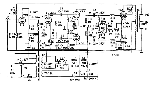
In April 1947, British "Radio World" magazine published DTN Williamson's article "High Quality Amplifier Design". An excellent power amplifier with large loop negative feedback is introduced in detail. This is the "Williamson Amplifier" that attracted worldwide attention. Although its distortion coefficient is above 5%, it has made a very satisfactory breakthrough in many other technical indicators compared with the previous amplifier. The basic circuit of this amplifier is shown in Figure 1, where VE1 is an input amplifier (also known as a pre-stage), VE2 is a PK split inverter, VE3 and VE4 constitute a driving stage, and VE5 and VE6 are push-pull output amplifiers (also Called the post level).
 figure 1
 The original "Williamson Amplifier" (hereinafter referred to as "Weiqi") is quite sophisticated in terms of structure and manufacturing process. Before the promotion level VE3, VE4 all used voltage amplification type transistors, and their models are L63. The basic characteristics of the tube are exactly the same as the American-made 6J5, Soviet-style bile 6C2C and domestic 6C2P, and the pins are the same, as shown in Figure 2 (a). The use of triodes for signal voltage processing can fully demonstrate the low internal resistance characteristics of this type of bile, which can improve the overall distortion of the amplifier and damp the resonance peak voltage of the speaker. The above are the advantages of the transistor voltage amplifier. The disadvantage of using a triode as a voltage amplifier is that its amplification factor (μ) is low, so it should have a large voltage excitation to have a sufficient output, which brings certain difficulties to circuit design. The next stage of the "weapon" is the multi-electrode tube KT66, and the quasi-triode is connected. The pins are shown in (b) of FIG. 2.
 figure 2
 The development of many things in the world often has a chance, and amplifier technology is probably no exception. Before the emergence of "weapon", there are also many well-known amplifiers, such as 6J7 + 6V6 + 2 × 2A3, 6J7 + 6J7 + 2 × 6L6, etc., but these amplifiers failed to overcome the large distortion, narrow frequency response, low power And other disadvantages. In early 1947, Williamson, an engineer working at the famous British tube manufacturer Marconi-Osram, discovered in an experiment that if the curtain grid of a pentode is connected to the screen to form a "quasi-triode", its The power output is increased by 30% compared with the original tube, and the distortion can be reduced by more than 40%. After finishing, it was published in April of the same year. This is the famous "Williamson amplifier" discussed above. The basic characteristics of "Weiqi" have six points:
(1) The whole machine uses triodes from front to back (the last stage uses inexpensive beam-emitting diodes for quasi-triode connection processing, which is also a "triode", which fully demonstrates the advantages of triodes.
(2) In order to meet the requirements of high excitation of the transistor, VE3 and VE4 are added as the driving stage of the power amplifier.
(3) From the pre-stage to the post-stage, the bias of each stage adopts a self-sufficient bias with excellent performance; and the self-sufficient bias resistors of each bile cathode are not connected with an AC bypass capacitor in parallel, so that it forms an effective AC / DC double feedback. This is of great interest in improving the stability of the circuit and widening the frequency band.
(4) Due to the increase in the number of stages, the self-excited factor of "weapon" has greatly increased. In order to maintain the stability of the circuit, in addition to the above-mentioned bias adopting AC / DC negative feedback technology, the G1 and G2 poles of the final stage VE5 and VE6 have also added special stabilizing resistors such as R19, R20, R22, R23; output transformer TO also made considerable effort in the winding process to prevent phase shift; a large loop negative feedback R21 was added to the secondary side of TO.
(5) In order to broaden the frequency band and suppress the phase shift, direct coupling is used between the input stage VE1 and the inverting amplifier VE2; at the same time, frequency compensation networks R5 and C2 are also introduced.
(6) In order to ensure the "synchronization" of the preheating at all levels, "Weiqi" adopts the rectifier power supply VE7. The power supply filter uses high-voltage non-polarized capacitors, and uses two sections of LC ripple suppressor, so the AC sound of the amplifier is very slight.
The "power tool" with the above characteristics has very good performance indicators, the output power reaches 15W, the harmonic distortion reaches below 3%, the frequency response is 20Hz to 20kHz (-3dB) when open loop, and 10Hz when closed loop ~ 100kHz (± 1dB). Moreover, the phase characteristics of open and closed loops are also ideal.
Later, many people also tried to transform the "weapon" (to smash), but most of them ended up with the result of "self-defense". This fully illustrates the integrity of the "weapon" and the advanced nature of the technology.
With the development of tube technology, people have made some useful attempts to use gallbladder at all levels while maintaining the original circuit program. After the appearance of the dual transistor, some people used the input stage VE1 and the inversion stage VE2 of the "weapon", some people used the large eight-legged 6SN7, and some people chose ECC82 or 12AU7 as the input and inversion stage, but the working state at this time should be slightly changed (Ua of VE1≈100V, Uk of VE2≈105V). Most of the driving grades VE3, VE4 and VE1, VE2 use the same type of tube, but some people use 12BH7. At this time, the anode resistance R12, R13 should be changed from 47kΩ to 33kΩ. The post-stage power amplifiers VE5 and VE6 usually use cost-effective beam power tetrode, such as KT66, 807, 6L6, 5881, 5933, etc., which are connected to "quasi-triode" and use transformer-coupled push-pull circuit. As we all know, the main disadvantage of the triode is that there is a large even harmonic distortion, and the transformer-coupled push-pull circuit is just the "can kill" even harmonic distortion. The combination of the two can promote the advantages and avoid the shortcomings, complement each other, making The return sound effect is very ideal. After the stage can also choose the new five pole bile EL34, the effect is also good.
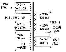
The Williamson amplifier made with domestic tubes is now introduced for reference when making tube amplifier enthusiasts. In the production process, the electronic tubes all choose excellent domestic gallbladders. At this time, the last stage VE5 and VE6 in Figure 1 can be replaced with domestic bile 6P14 (the suppression grid is connected to the cathode in the tube), VE1 to VE4 are replaced with two bipolar transistors 6N1, and the power rectifier VE7 is replaced with 5Z3P. The post-stage working point is designed in Class A and Class B. The main technical parameters of the domestic 6P14 are shown in the attached table. Because the technical parameters of 6P14 and KT66, 807 and other gallbladders of the original "weapon" are quite different, the corresponding power transformer TP and output transformer TO should also be properly adjusted. TP has no finished product and needs to be wound by itself. The core uses GEB / GIB-22, with a tongue width of 30mm and a stack thickness of 38mm. The material properties are D310-0.35 / 10000, and Wr = 6.4 turns / volt. The schematic diagram is shown in Figure 3. The wire used for TP is as follows: N1 ![]() It is 0.3 line 1408, N2-1 is
It is 0.3 line 1408, N2-1 is ![]() 0.27 line 1600T × 2, N2-2 is
0.27 line 1600T × 2, N2-2 is ![]() 1.38 line 32T, N2-3 is
1.38 line 32T, N2-3 is ![]() 1 line 20T × 2, N2-4 is
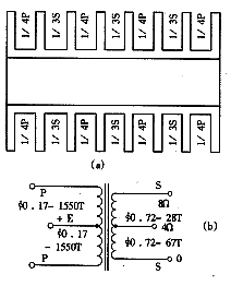
1 line 20T × 2, N2-4 is ![]() 1.45 line 40T. The winding method is according to the layering and inter-segment winding method. The specific process is introduced in many books and periodicals, and will not be described in detail. The output transformer TO can choose U6012 or Ding brand CB17W8. If self-made, GEB / GIB-22-D310-0.35 / 10000 iron core can be used, the cross-sectional area is Sc = 22 × 28, and the wire and wire system parameters are shown in Figure 4, where the skeleton [Figure 4 (a)] is a multi-slot structure , Primary and secondary windings are arranged in sections. Other components also use high-quality domestic products. The resistor is a flame retardant coated metal film resistor. C5 ~ C8 use XINDAK / P series CBB capacitors, C2 use mica capacitors, C9 ~ C11 are color TV high-voltage electrolytic capacitors CD291 (100μF / 400V), other power filter electrolytic capacitors C1, C3, C4 etc. are CD293 (33μF / 400V) . Inductors L1 and L2 use "Lishen" products. RP1, RP2 use solid fine-tuning potentiometer.
1.45 line 40T. The winding method is according to the layering and inter-segment winding method. The specific process is introduced in many books and periodicals, and will not be described in detail. The output transformer TO can choose U6012 or Ding brand CB17W8. If self-made, GEB / GIB-22-D310-0.35 / 10000 iron core can be used, the cross-sectional area is Sc = 22 × 28, and the wire and wire system parameters are shown in Figure 4, where the skeleton [Figure 4 (a)] is a multi-slot structure , Primary and secondary windings are arranged in sections. Other components also use high-quality domestic products. The resistor is a flame retardant coated metal film resistor. C5 ~ C8 use XINDAK / P series CBB capacitors, C2 use mica capacitors, C9 ~ C11 are color TV high-voltage electrolytic capacitors CD291 (100μF / 400V), other power filter electrolytic capacitors C1, C3, C4 etc. are CD293 (33μF / 400V) . Inductors L1 and L2 use "Lishen" products. RP1, RP2 use solid fine-tuning potentiometer.
 image 3
  Figure 4 Schedule
 | Serial number | parameter name | Code | unit | parameter | Remarks |
| 1 | Filament voltage | Uf | V | 6.3 | 5.9 ~ 6.9V |
| 2 | Filament current | If | mA | 760 | 710 ~ 830mA |
| 3 | Anode voltage | Ua | V | 300 | Screen ~ Blood voltage |
| 4 | Static screen flow | Iao | mA | 48 | Static operating point |
| 5 | Full signal screen flow | Iam | mA | 52 | Ia = 4mA |
| 6 | Cathode self-bias resistance | Rk | Ω | 270 | Eg≈-13V |
| 7 | Grid / gate excitation | Ugg | V | 20 | Effective value (RMS) |
| 8 | Output Power | PO | W | 5 | Rated output power |
| 9 | Screen / Screen best load | Raa | k | 10 | TO should match |
| 10 | Harmonic distortion | THD | % | 3 | In most cases less than 2.5% |
The debugging of this machine is relatively simple, and VE1 ~ VE4 basically need not be adjusted; the latter stage first adjusts RP2 to make the cathode voltage of VE5 and VE6 about 13V, and then adjusts RP1 to balance the two arms (the voltages at points a and b are both 2.4 V). After the tuning is completed, the machine can reach the technical indicators: Po ≥ 5W, THD ≤ 2.5%, FR = 22Hz ~ 30kHz (± 1dB). If you need to use dual channels, you can assemble two sets of the same circuit with domestic components according to Figure 1. |

Follow WeChat

Download Audiophile APP

Follow the audiophile class
related suggestion