As mentioned earlier, a linear regulator is a type of integrated voltage regulator that uses a transistor or FET that operates in a linear region to subtract excess voltage from the applied input voltage to produce a regulated output voltage. The function of the linear regulator is to provide a stable DC output voltage when the input voltage or load changes within the specified operating range, and to ensure that the regulator circuit can work safely and reliably for a long time.
A common integrated linear regulator is also called a standard linear regulator or an NPN linear regulator. The standard linear regulator is mainly composed of a basic part such as a reference voltage source, a sampling circuit, an error amplifier, and an adjustment tube.
The basic working principle of standard linear regulator
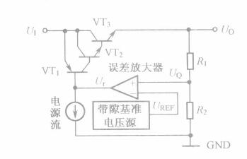
The basic principle of the standard regulator is shown in Figure 1. The series regulator is a Darlington tube composed of NPN transistors VT2 and VT3. VT1 is a drive tube that uses a PNP transistor. U1 is the input voltage and U0 is the output voltage. R1 and R2 are the sample-receiving resistors, and the sampling voltage UQ is applied to the non-inverting input terminal of the error amplifier. Compared with the reference voltage UURE applied to the inverting input terminal, the difference between the two is amplified by the error amplifier to generate an error voltage Ur. Adjust the voltage drop of the series regulator to stabilize the output voltage. For example, when the output voltage U0 decreases, both UQ and UR decrease, and as the drive current increases, the voltage drop of the adjustment tube decreases, causing the output voltage to rise.
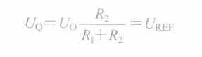
Conversely, if the output voltage U0 rises, the drive current output from the error amplifier decreases, and the voltage drop of the adjustment tube increases, causing U0 to drop, and finally U0 remains stable. Since the feedback loop always tries to equalize the potentials at the two inputs of the error amplifier, ie U0=U REF , according to the above figure, we can get:
Need to explain a few points:
First, the output voltage is controlled by a feedback circuit that requires compensation to ensure loop stability. Some linear regulators have a built-in compensation circuit that eliminates the need for external compensation components to achieve stable operation of the linear regulator. Some linear regulators require an external compensation network.
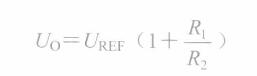
Second, the feedback loop for controlling the output voltage "judges" the output voltage through the sampling resistor, and sends the sampled voltage to the non-inverting input of the error amplifier, and the reference current is connected to the inverting input. This means that the error amplifier will equalize the sample voltage to the reference voltage by constantly adjusting its output voltage and adjusting the tube current. The output voltage of a linear regulator is typically several times the reference voltage.
Third, the current through the resistor dividers R1 and R2 is negligible compared to the load current.
Fourth, to squib the tube VT1, a PNP transistor must be used. This is because the emitter junction voltage UBE of the NPN transistor is a positive voltage, and U B >U E , that is, U B >U 1 is obviously unreasonable; The U BE of the PNP tube is a negative voltage and can satisfy the requirement of U B <U E , that is, U B <U 1 .
Fifth, Figure 1.2.2 is only a simplified circuit. In the actual circuit, a starting circuit, an overcurrent protection circuit, and an overheat protection circuit are also required.
A slip ring is an electromechanical device that allows electricity and data to pass through a rotating assembly. A mercury slip ring uses liquid mercury as the electrically conductive element inside the rotating assembly, as opposed to traditional carbon brushes. Mercury is a better conductor of electricity than carbon, and it also has a very low contact resistance. This makes it an ideal choice for applications that require high-speed data transmission or where reliability is critical. Mercury slip rings are used in a variety of industries, including medical technology, aerospace, and defense.
Why do we choose a mercury slip ring?
A slip ring is an electromechanical device that allows electrical current to pass between rotating objects. Slip rings are often used in applications where a cable or connector would otherwise twist and tangle as the object rotates. There are many different types of slip rings, but one of the most common is the mercury slip ring. Mercury slip rings offer several advantages over other types of slip rings, including high reliability, low maintenance, and long life. Here are three reasons why we choose a mercury slip ring:
1. Reliability: Mercury is an extremely reliable material, and mercury slip rings are among the most reliable types of slip rings available. Mercury has a very low failure rate, and it is not affected by changes in temperature or humidity. This makes mercury slip rings ideal for critical applications where reliability is essential.
2. Low Maintenance: Mercury slip rings require very little maintenance. Because mercury is a very inert substance, it does not corrode or generate any corrosive gases that would affect its reliability. Mercury slip rings do not require any lubrication, and they can operate in a wide range of temperatures and environments.
3. Economical Mercury slip rings have a lifetime cost advantage over other types of slip rings as well. Generally speaking, mercury slip rings are approximately 25% more expensive per kilowatt than other types of slip rings. However, because they require less maintenance and have a greater degree of reliability than other types of slip rings, they will save you money over the lifetime of your equipment.
Mercury Slip Ring,Slip Ring Gigabit Ethernet,Slip Ring 400V,Slip Ring Pneumatic
Dongguan Oubaibo Technology Co., Ltd. , https://www.sliproub.com