Several common
Weighbridge
Load cell
of
Technical characteristics and application analysis
The load cell is called
Weighbridge
The heart part. This article mainly elaborates
Weighbridge
Resistance strain gauge, electromagnetic force, photoelectric, capacitive, hydraulic, vibration, magnetic pole deformation, gyro ceremony, fiber grating
9
Large class of load cells are introduced and analyzed separately, which is beneficial to the weighing and sensing technology workers to further understand and master relevant knowledge.
I. Overview
The three foundations of modern information technology are information acquisition, transmission and processing technologies, namely sensing technology, communication technology and computer technology. They constitute the "sensory", "nerve" and "brain" of the information technology system. The primary component of the information acquisition system is the sensor and is placed at the forefront of the system. In a modern automatic detection system, if there is no sensor, it is impossible to monitor and control various parameters of each link in the production process, and automatic control cannot be realized. In modern technology, sensors are actually the foundation of modern test and automation technologies.
The load cell is called
Weighbridge
The heart part. With the rapid development of science and technology, made by load cells
Weighbridge
It has also been widely used in all walks of life to achieve fast and accurate weighing of materials. Especially with the advent of microprocessors, the degree of automation of industrial production processes continues to increase, and load cells have become an essential device in process control. At present, load cells are used in almost every industry.
Weighbridge
The load cell is usually divided into resistance strain gauge, electromagnetic force, photoelectric, capacitive, hydraulic, vibration, magnetic pole deformation, gyro ceremony, fiber grating according to the conversion method.
9
The largest category is the most widely used with resistance strain gauges. Here are a few common ones
Weighbridge
The working principle, characteristics and comparison of the advantages and disadvantages of the load cell.
Second, resistance strain gauge load cell
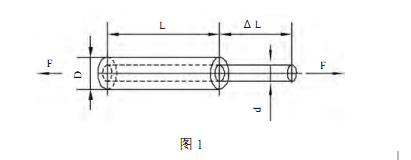
A resistance strain gauge with a metal material as a conversion element, the conversion principle is based on the resistance of the metal resistance wire—
Strain effect, the so-called strain effect refers to a physical phenomenon in which the resistance value of a metal conductor (resistance wire) changes with deformation (elongation or shortening) (as shown in the figure).
1
Shown).

The resistance value of the metal conductor can be expressed by the following formula:
R=P
â–³
L/
â–³
S
In the formula:
P
- the electrical resistivity of the metal conductor (Ω
.C
M2
/m
)
;
S
- the cross-sectional area of ​​the conductor (
c
M2)
;
L
- the length of the conductor (
m
)
.
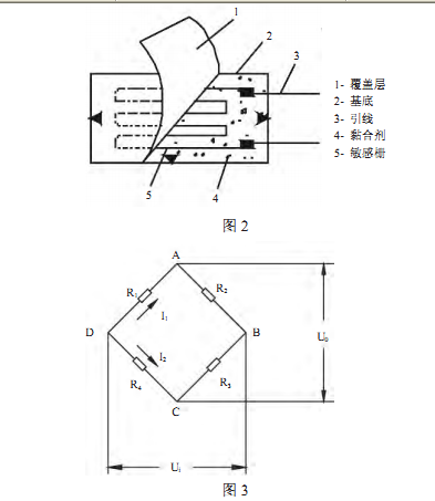
The resistance strain gauge type load cell is based on the principle that the elastic body (elastic element, sensitive beam) is elastically deformed under the action of an external force, so that the resistance strain gauge attached to the surface thereof is
2
The deformation is also accompanied by deformation. After the strain gauge is deformed, its resistance will change (increase or decrease).
Wheatstone bridge (pictured
3
Shown) This resistance change is converted into an electrical signal (voltage or current), thereby completing the process of converting an external force into an electrical signal.

The resistance strain gauge load cell has a weighing range of tens of grams to several thousand tons, and the measurement accuracy is up to
1/1000
~
1/10000
, the structure is simpler, the reliability is better, most of them
Weighbridge
Use this sensor
The resistance strain sensor has the advantages of high accuracy, wide measuring range, long life, simple structure and good frequency response characteristics.
It can work under severe conditions, and it is easy to achieve miniaturization and variety. Its shortcomings are mechanical hysteresis, creep and zero drift, strain limit, large nonlinearity for large strain, weak output signal, but can be improved by certain measures. The resistance strain gauge load cell is the most widely used load cell, and its characteristics are also the most studied.
Third, the electromagnetic force balance weighing sensor
The weighing process of the electromagnetic force balance sensor is based on Ampere force. The force exerted by the energized wire in the magnetic field is shown in the figure
4
Shown. A weighing pan is added to the wire, and the weighing plate and the wire itself have a gravity direction facing downward, and the energizing wire receives an upward electromagnetic force. When the current value passing through the wire reaches a certain value, the two forces are balanced with each other. The sensor is in equilibrium to determine the weight of the object being measured. The electromagnetic force balance sensor relies on the gravity balance of the electromagnetic force generated by the current-carrying coil in the constant DC magnetic field and the measured mass to realize the electrical signal conversion of the measured mass.

Electromagnetic balance load cell is a high precision sensor with high precision
1/2000
~
1/60000
However, the weighing range is only between tens of milligrams and ten kilograms. Widely used in electronic analytical balances, it is a commonly used sensor for precision mass weighing. Due to its high resolution, sensitivity, and price, it is widely used in precision mass weighing, chemical reaction monitoring, acceleration measurement, and moisture detection. In order to reduce the size of the sensor, simplify the manufacturing process of the sensor, and reduce the manufacturing cost, the constant DC magnetic field of the electromagnetic force balance sensor uses a permanent magnet. The permanent magnet acts as a permanent magnet of the electromagnetic force balance sensor, and the stability of its magnetic properties directly affects the accuracy of the electromagnetic force balance sensor.
The electromagnetic force balance sensor is a relatively mature patented technology, which requires high requirements for the production conditions of the sensor. At present, only a few large manufacturers in the world master this technology. This high-precision electronic weighing device is highly accurate due to its unique working principle and process level, and is mainly used in the high-end market. For example, a single-module sensor made of high-strength aluminum alloy material by high-precision electric spark cutting, METTLER, Switzerland
-
Both the Toledo Group and the German Sartorius have this patented technology. He combines the levers of the traditional electromagnetic force balance sensor, the upper and lower guides, the base and the reeds. Thanks to the internal connectionless screws, the reliability is greatly improved, and the high-efficiency mechanical transmission performance and torque protection improve the service life.
Fourth, capacitive load cell
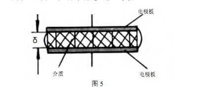
A capacitive load cell is a sensor that converts the measured mechanical quantity, such as displacement, pressure, etc., into a change in capacitance. Its sensitive part is a capacitor with variable parameters, the most common form of which consists of two parallel electrodes
a capacitor with air as the medium (as shown in the figure)
5
Shown).

He uses the oscillation frequency of the capacitor oscillation circuit
f
Pitch spacing
Q
The positive proportional relationship works. If the edge effect is ignored, the capacitance of the plate capacitor is:
C=
∑
A/Q
Where: ∑—the dielectric constant of the interpolar medium;
A
- the effective area covered by the two electrodes;
Q
- the distance between the two electrodes.
Oh,
A
,
Q
Any change in any of the three parameters will cause a change in capacitance and can be used for measurement. Therefore, the capacitive sensor can be classified into three types: a pole-distance change type, an area change type, and a medium change type. The pole-distance type is generally used to measure minute line displacements or pole-distance changes due to force, pressure, vibration, and the like.
The advantages of the capacitive load cell are simple structure, low price, high sensitivity, strong overload capability, low power consumption, low cost, and accuracy.
1/200
~
1/500
, dynamic response characteristics, high temperature, radiation
Strong adaptability to harsh conditions such as strong vibration. The disadvantage is that the output has nonlinearity, parasitic capacitance and distributed capacitance, which have a great influence on sensitivity and measurement accuracy. Because the resistance strain gauge load cell can not be made into ultra-high temperature or the failure rate is very high in the ultra-high temperature environment, the capacitance scale is usually used when the accuracy of the symmetry quantity is not high in many ultra-high temperature environments or only for the safety overload protection. Heavy sensors have certain advantages, such as some high-temperature hook scales used in steel mills, which are currently very rare.
Five, photoelectric load cell
Photoelectric sensors include both grating and coded discs.
The working principle of the grating sensor is to convert the angular displacement of the moiré fringes formed by the grating into photoelectric signals. The grating has two pieces, one of which is mounted on the dial shaft and the other is fixed. After loading the weight, the force-transmitting lever drives the dial shaft to rotate, which causes the moving grating to rotate, and the moiré stripes move accordingly. Photocell
The conversion circuit and the display instrument calculate the number of removed moire fringes and measure the rotation angle of the grating to determine and read the mass of the measured object.
The code wheel (symbol plate) of the code wheel sensor is a transparent glass mounted on the dial shaft with black and white codes coded according to a certain coding method. After loading, the dial is also rotated through a certain angle when the dial shaft is rotated by the lever. The photocell receives the optical signal through the code wheel and converts it into an electrical signal, which is processed by the circuit and the measurement result is obtained.
Photoelectric sensors have been mainly used in electromechanical combined scales, which have the advantages of stable working and anti-interference ability. They can be used in industrial environments such as harsh coal mines, but the running speed is low and cannot meet the requirements of high-speed weighing.
In recent years, due to the maturity of the technology of resistance strain gauge load cells, such sensors have basically no more
Application, as a transitional product once completed its mission, almost exited the market.
Sixth, hydraulic load cell
The hydraulic load cell means that when the gravity of the object under test is applied, the pressure of the hydraulic oil increases, and the degree of increase is proportional to the gravity of the object. When the pressure is increased, the mass of the measured object can be obtained. The hydraulic sensor has a simple and firm structure and a large measuring range, but the accuracy is generally less than
1/1000
Sometimes even
1/100
Not too much. It is currently mainly used in weighing and measuring applications where the accuracy of the symmetry is not high or the safety overload protection is concerned, such as a loader scale.
Seven, magnetic pole deformation type load cell
When the ferromagnetic element of the magnetic pole deformed load cell is mechanically deformed by the gravity of the object under test, stress is generated internally and the magnetic permeability changes, so that the induced voltage of the secondary coil wound around the ferromagnetic element (magnetic pole) also follows Change
. Measuring the change in voltage
The amount of force applied to the magnetic pole can be determined to determine the mass of the measured object.
.
The accuracy of the magnetic pole deformation sensor is not high, generally
1/100
Suitable for large tonnage weighing work
.
Almost in the whole
There is no practical application in the heavy sensor market.
Eight, vibrating load cell
After the elastic element is stressed, the natural vibration frequency is proportional to the square root of the force. When the change of the natural frequency is measured, the force of the object to be applied to the elastic element can be obtained, and the mass can be obtained. Vibrating sensors are available in vibrating wire and tuning fork.
The elastic element of the vibrating wire sensor is a string. When the object to be tested is added to the load-bearing platform,
V
The intersection of the chord is pulled downward, and the pulling force of the left chord is increased, and the pulling force of the right chord is decreased. The natural frequencies of the two strings vary differently. Find the difference between the frequencies of the two strings to find the mass of the measured object. Vibrating wire sensors have higher accuracy and reach
1/100
0 ~ 1 / 10000, weighing range from 100 grams to hundreds of kilograms, but the structure is complex, processing is difficult, and the cost is high.
The elastic element of the tuning fork sensor is a tuning fork. A piezoelectric element is fixed to the end of the tuning fork, which oscillates at the natural frequency of the tuning fork and can measure the oscillation frequency. When the object to be tested is added to the load-bearing table, the direction of the tuning fork is forced and the natural frequency is increased. The degree of increase is proportional to the square root of the applied force. When the change of the natural frequency is measured, the weight is applied to the tuning fork. The force, and then the weight of the weight. The tuning fork sensor consumes a small amount of electricity, and the measurement accuracy is as high as 1/10000 to 1/200,000, and the weighing range is 500g to 10kg.
Nine, gyro ceremony load cell
When analyzing the movement of the gyro from a mechanical point of view, it can be regarded as a steel body. The rigid body has a directional pivot point, and the gyro can rotate around the fulcrum with three degrees of freedom. Therefore, the movement of the gyro is It belongs to the rotational movement of a rigid body around a fixed point. More specifically, a flywheel rotor that rotates at high speed around the axis of symmetry is called a gyro. The gyroscope is mounted on the frame device so that the autorotation axis of the gyroscope has an angular rotation degree. The overall device is called a gyroscope.
The basic components of the gyroscope are:
1. Gyro rotor (usually using synchronous motor, hysteresis motor, three-phase AC motor and other drag methods to make the gyro rotor rotate around the rotation axis at high speed, and see its speed is approximately constant).
2.
Inner and outer frames (or inner and outer rings, which are structures that allow the gyro's rotation axis to achieve the desired angular rotational freedom.
3.
Accessories (referring to torque motors, signal sensors, etc.).
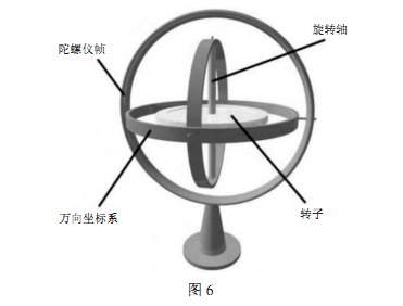
As shown
6
As shown, the rotor is mounted in the inner frame and is wound at angular velocity.
X
The shaft rotates stably, and the inner frame is coupled to the outer frame via the bearing and can be wound around the horizontal axis.
Y
Tilting rotation, the outer frame is coupled to the base by the universal joint, and can be wound around the vertical axis
Z
Rotation, rotor shaft (
X
The shaft is horizontal when it is not subjected to an external force, and one end of the rotor shaft is inclined while being subjected to an external force and is wound around the vertical axis.
Z
Turn. Precessional angular velocity and external force
P/2
Proportional, measured by the method of detecting frequency
W
Then, the magnitude of the external force can be obtained, and the mass of the measured object that generates the additional force can be obtained.

Gyro ritual sensor response time is fast (
5
Second), no hysteresis, good temperature characteristics, small vibration impact, high accuracy and accurate frequency measurement, so high resolution can be obtained (
1/100000
And high measurement accuracy (
1/3000
0 to 1/60000).
Ten, fiber grating type load cell
The fiber grating type load cell is a kind of fiber sensor. The fiber grating based sensing process is to obtain the sensing information by modulating the fiber Bragg wavelength by external physical parameters, and is a wavelength modulation type fiber sensor.
Fiber Bragg Grating sensors enable direct measurement of physical quantities such as temperature and strain. Since the wavelength of the fiber grating is sensitive to both temperature and strain, that is, temperature and strain simultaneously cause the wavelength of the fiber grating coupling to move, so that the temperature and strain can not be distinguished by measuring the wavelength shift of the fiber grating coupling. Therefore, solving the cross-sensitive problem and realizing the differential measurement of temperature and stress is the premise of the practical use of the sensor. Temperature and stress differential measurements are achieved by certain techniques to determine stress and temperature changes. The basic principle of these techniques is to use two or two fiber gratings with different temperature and strain response sensitivities to form a double grating temperature and strain sensor. By determining the temperature and strain response sensitivity coefficients of the two fiber gratings, two binary The equation solves the temperature and strain.
The fiber gratings used in the experiments are all BRAGG fiber gratings, and the refractive index modulation period is uniform, so the BRAGG condition is satisfied, that is,

It can be seen from the above that the fiber grating BRAGG wavelength change is only related to the change of the stress and is proportional to the change of the temperature change. According to this principle, the fiber grating can be used to measure the change of the force.
Fiber Bragg Grating Load Cells have the following advantages:
1. Anti-electromagnetic interference: The frequency of general electromagnetic radiation is much lower than that of light waves, so the optical signal transmitted in the optical fiber is not affected by electromagnetic interference.
2. Electrical insulation performance is good, safe and reliable: the optical fiber itself is composed of dielectric and does not need power supply. Therefore, it is suitable for use in flammable and explosive oil, gas and chemical production.
3. Corrosion resistance, stable chemical properties: Due to the high chemical stability of the material used to make the fiber, the fiber sensor is suitable for use in harsh environments.
4. Small size, light weight and geometric shape.
5. Small transmission loss: remote remote monitoring can be realized.
6. Large transmission capacity: multi-point distributed measurement can be realized.
7. Wide measurement range: can measure temperature, pressure, strain, stress, flow, flow rate, current, voltage, liquid level, etc.
At present, most of the fiber grating load cells are still in the research and experimental stage. There are reports at home and abroad. The German HBM company already has optical fiber grating-based optical strain gauges, and has been successfully applied to DB MINDEN for HBM. Optical strain gauges are used for the latest railway vehicle testing.
This article is from (Shanghai Xinying Weighing Apparatus Co., Ltd.)
Shanghai Head Office Address: Nanfeng Highway, Fengxian District, Shanghai
5108
number
Production base: Yanxiu Road, Qingpu District, Shanghai
788
number
Jiangsu Production Base: Chuangye Road, Industrial Zone, Lishui County, Huai'an City
88
number
total
machine:(
021
)
60548466
pass
true:(
021
)
33616158
Weighbridge sales hotline:
13818755070
Manager Zhao
Online buckle:
149597530
Electricity
words:(
021
)
60548466
pass
true:(
021
)
33616158
Service Hotline:
400 000 4208
CAT6 rj45 Keystone Jack is a part of networking cabling solutions for patch panels, wall mounting plates,face plates, surface mount boxes with T568A T568B standard wiring. It could get 10G+ Ethernet calbing solutions with more conveniet, low price and cost effective in various packing customized.
The contacting point is finished by gold plated, and easy snap into retaining clip to make sure corrosion connecting freely and security.
CAT6 Keystone Jack,Keystone Jack CAT6,Cat6 keystone,cat6 keystone coupler
NINGBO UONICORE ELECTRONICS CO., LTD , https://www.uonicore.com