Abstract: This paper introduces in detail the application of DC-DC converter in electric vehicles, as well as its test methods for voltage accuracy, efficiency, linearity/load regulation and transient response, focusing on the Itech IT8900. The advantages of power DC load in DC-DC testing and the features of the ITS9500 power test system.
textDC-DC converters are common power converters on the market and are widely used in various industries, such as UPS power supply, electric vehicles, photovoltaic energy storage systems, and aviation energy storage systems. They are used to convert DC high voltage into low voltage or low voltage. Convert to high pressure. Testing DC-DC converters is critical to determining their performance, safety, and efficiency conversion rates. In the following, a new energy vehicle is taken as an example to introduce the use of the DC-DC converter and the related test items involved in the output, focusing on the test advantages of the ITECH IT8900 high-power DC load.
Application of DC-DC converter in new energy vehiclesMost electric and hybrid electric vehicle configurations use two energy storage devices, the high energy storage device, also known as the "main energy system" (MES), and the other with an inverter energy system, also known as the "rechargeable energy system" (RESS). ). As shown in Figure 1, an electric vehicle can be powered by a fuel cell, a power battery pack, and a supercapacitor at the same time, which can effectively reduce cost, size, and performance.
The DC-DC converter is a core component of the auxiliary power supply in a hybrid vehicle. The converter needs to convert energy from a 12V DC bus to a high voltage DC bus (for electric traction). The power of the DC-DC converter is determined by the characteristics of the car, such as the highest speed, 100 km acceleration, weight, maximum torque and power conditions (peak power, continuous power). In general, passenger car converter power is generally greater than 20 KW, up to 100 KW.
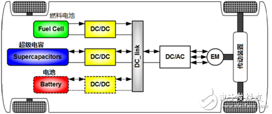
Figure 1. Electric vehicle drive system 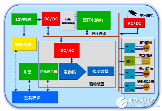
Figure 2. Hybrid power transmission block diagram
The diagram in Figure 2 shows the power supply inside the hybrid car. The service battery provides 12V standard voltage for instrument panels, brakes and lighting. The 200-800V high voltage power supplied by the power battery is used in the traction system. The power battery can be charged by the hybrid control system and/or the power grid via an AC-DC converter, while the 12V battery is charged by the power battery by a DC-DC converter. Therefore, the configuration of the electric vehicle can use a two-way or one-way system. The reliability of the converter is a key factor, because a small error will cause the discharge of the 12V service battery, which directly leads to the loss of the entire electronic system.
Test method for DC-DC converterTests on DC-DC converters include efficiency testing, dynamic response testing, on-off time testing, protection testing, and the like. These tests can be automated using the ITECH ITS9500 power test system and are used in product development, design verification, mass production, incoming or inspection testing, and qualification testing. Below I will focus on the application of the high-precision high-power DC load IT8900 series in the power test system in the relevant test items in the DC-DC converter. The IT8900 series electronic load power range from 12KW to 600KW, which can fully meet the testing requirements of high-power DC-DC converters.
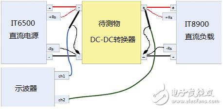
Figure 3. Test wiring for DC-DC converter
Test open, shutdown voltage and time: As shown in Figure 3, for the DC-DC converter to be tested, the pre-amplifier input voltage has a certain working range. In order to verify the input voltage range, a programmable DC power supply is required. Dex IT6500, IT6700H, IT6900 series electronic load). DC loads IT8900, IT8800, and IT8500+ can be used to pull current and simulate post-stage equipment.
Test the minimum input voltage, use the rated voltage input after the DC-DC converter is turned on, and load the full current (full power) to load. Reduce the input voltage until the output drops or decreases to the minimum input voltage.
In order to verify that the DC-DC converter can be started when the rear stage is fully loaded, the input voltage can be set to minimum, turn off and on, and the voltage and current at the output can be measured. The output voltage and ripple are measured to observe the effect of low input voltage on output stability and ripple. In order to ensure test accuracy, the remote measurement terminals of the power supply and load must be connected.
Test open, shutdown, hold time, you can use the time measurement function of Itech IT8900 DC load, can test the rise and fall time of voltage and current waveforms, internal 18bit, 500kbps high-speed AD sampling, test accuracy can reach 10 microseconds , comparable to high-precision oscilloscope, as shown in Figure 3. The Aidex power supply and load are open to the customer's programming instructions. Customers can not only use their own software for PC operation or system operation, but also build their own intelligent test platform.

Figure 3. Comparison of the measurement of current drop time and the measurement results of high-precision oscilloscope by IT8900
The power-on time is the time from the minimum input voltage to the time when the output voltage reaches the specified output value. The shutdown time is from the time the input voltage drops to the minimum input voltage until the output is turned off or the voltage drops to 0V. As shown in Figure 4.
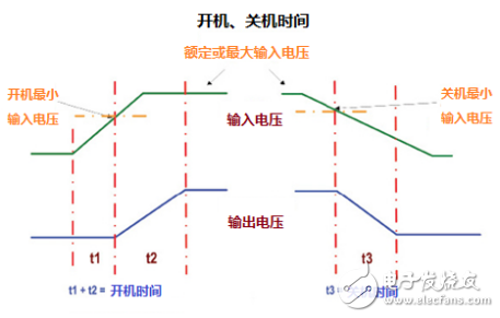
Figure 4, switch time
The hold time measurement uses the same test wiring, which is the time from the input drop to the minimum input voltage until the output voltage drops to the minimum operating voltage. This test indicates the stability of the output of the DC-DC converter when the input has a short interruption or a voltage drop. Some DC-DC converters have an input failure detection signal that can also be used as a switch to trigger this test.
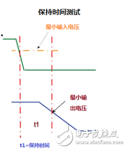
Figure 5, retention time
Output Linear Rate Test: This test measures the range of the DC-DC converter output voltage when the input voltage changes from the minimum operating voltage to the maximum operating voltage, whether it meets the specification.
The output linearity test includes monitoring the output voltage, changing the input voltage (from minimum to maximum) and recording the output voltage deviation (in absolute or percentage).
If the measurement accuracy of the output load is comparable to the accuracy of the input DC power supply, then there is no need to add a digital multimeter (DMM) to measure voltage, current and power. For example, Itech's IT8900 DC load and IT6500 DC power supply have comparable voltage, current, and power test accuracy, so there is no need to add an external DMM meter. Test systems often include an oscilloscope or an oscilloscope card to verify the stability of the output voltage.
The output linear adjustment rate Ro can be calculated using the following formula:

Among them, Vomax is the output voltage at the maximum input voltage; Vomin is the output voltage at the minimum input voltage; Vonom is the output voltage at the rated input voltage.
Output Load Regulation Rate: The output load regulation rate test ensures that the output voltage of the DC-DC converter is stable within the nominal value. Here, the change in output voltage varies with the magnitude of the load current and is recorded. The voltage difference is used to calculate the percentage of the load regulation rate deviation. The calculation formula of the load regulation rate Lr is as follows:

Among them, Voio is the output voltage at the maximum load current; Voim is the output voltage at the minimum load current; Vonom is the output voltage at the typical load current.
Transient Response Deviation and Time: This test is used to reflect the response of the DC-DC converter output voltage to output current transients, including the maximum output voltage offset and the time to return to the specified voltage value.
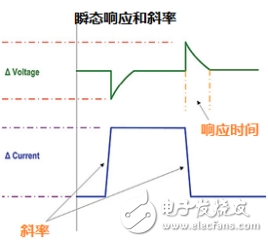
Figure 6. Transient response voltage offset and recovery time
The test method is to first set the large current and small current of the load pull, and set the current rise, fall slope, frequency and duty cycle. The ITECH IT8900 high-precision DC load supports dynamic load-carrying programming with a frequency up to 25KHz, a rising and falling slope of up to 10A/us, and a duty cycle that can be set anywhere from 1% to 99%.
User Load (Waveform) Simulation: Some DC-DC converter post-stage loads have their own specificity, pulling carrier shape and dynamic changes to unconventional waveforms. The electronic load such as the ITECH IT8900 can simulate the waveform of the real load, and the rising and falling slope can be as high as 10A/us, and the waveform data can be stored in the machine memory or through the built-in GPIB, LAN, USB, RS232 and other interfaces, remotely controlled by the host computer software. Control and save and export data.
Efficiency test: Efficiency reflects the effectiveness of the DC-DC converter to convert electrical energy from the input to the output. When testing efficiency, the input and output terminals are often rated input and output voltage. The efficiency Ep is calculated from the following formula:
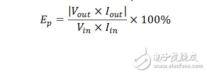
Among them, Vout and Iout are the output voltage and current; Vin and Iin are the voltage and current at the input of the converter. The high-precision load of the IT8900 series can test voltage and current with up to five-thousandths of a percent. This test can test the conversion efficiency under different load-carrying powers, and can plot the relationship between efficiency and output current.
Standard DC-DC converter test items include voltage accuracy, efficiency, linear/load regulation, and transient response. The ITECH ITS9500 power test system has built-in modular AC/DC power supply, AC/DC load, switch analyzer (IO card, relay card, DSO card) to meet the customer's DC-DC converter for power, accuracy and speed. The test requirements, modular design adds design flexibility.
in conclusion:The performance of the DC-DC converter is critical to the stable and reliable operation of the system. Whether it's pre-production design verification or evaluating DC-DC converters for a certain type of product, a process that can be repeated and accurately tested is required.
This paper introduces the advantages of ITECH electronic load IT8900 in DC-DC converter test: built-in high-precision digital voltage and current meter, and time measurement function with high-precision voltage and current waveform, built-in rich communication interface, supporting There is related PC software and open SCPI communication protocol to facilitate customers to set up an intelligent test platform. At the same time, the ITECH ITS9500 power test system can measure more than 40 test items, which can meet the more comprehensive test requirements of DC-DC converters.
Opzs Series 2V100Ah Battery,Opzs Series Solar Power Battery,Lead-Acid Opzs Batteries,Opzs Solar Tubular Batteries
Shaoxing Honyo International Trading Co., Ltd , https://www.honyopower.com