First, the introduction
Arkla Pipeline Group has studied a vehicle-mounted sonic nozzle verification device that can calibrate gas turbine flowmeters under actual operating conditions. The measured flowmeter diameter is 3-16 in. This calibration system is combined with a gas chromatograph to perform gas mass flow calculations.
This verification system has been greatly improved over the past methods. In most cases, the turbine flow meter calibrated at atmospheric pressure is used for operation and the original meter constant will drift. The use of sonic nozzles under actual working pressure and temperature conditions overcomes this deficiency. In addition, the sonic nozzle system uses natural gas as the medium instead of air, and also removes errors introduced by air.
The on-board calibration system can characterize the entire turbine metering system, not just a turbine meter. This means that errors caused by pulsations can be detected, which is not possible with any other calibration system.
Second, the basic definition of the definition of the sonic nozzle flow is: when the other parameters remain unchanged, when the pressure downstream of the nozzle drops to a certain point, even if the downstream pressure continues to decline, it will not cause the mass flow of the nozzle throat to further increase . At this point, the velocity of the gas at the nozzle throat is the speed of sound, known as "critical flow", "sonic flow" or "turbulent flow". The mass flow of the gas can be accurately determined at the nozzle throat. In the early days, the speed of sound was obtained when the pressure at the inlet and outlet of the nozzle was reduced to 50%. However, the pressure drop can now be as small as 5%, and the typical pressure drop does not exceed 10%, that is, the speed of sound can be obtained.
Third, the equipment of the vehicle verification device
1. A car board room is divided into a microcomputer room, a valve block room, an air compressor room and a power supply room. This separates the danger zone from the non-hazard zone.
2. A computer control system, including an IBM. The 386 microcomputer has a 120 megabyte hard drive with 32 printers and a remote terminal (RTU). The remote terminal is the interface between the microcomputer and the digital control valve. It has control output, status input and analog input control output switch solenoid valve - each nozzle has a solenoid valve. Each actuator is provided with a status input signal by two reed switches, reflecting the position of the actuator, and the microcomputer determines which nozzles are in operation. The status input signal from the air compressor can indicate whether the air pressure drops below 751b/in2 (table), which is the minimum operating pressure of the digitally controlled valve. The simulated input represents the operating temperature and pressure of the turbine flow meter (two inputs), the pressure at the valve inlet and outlet (three-point input), and the temperature at the valve inlet (one-point input).
3. A Daniel gas chromatograph, which is a key device in the calibration system. The gas chromatograph performs a real-time component analysis of the gas every 6 minutes and passes the result through an RS. The 232 communication interface is delivered to the computer. Computer application molecular percentages calculate two variables for the mass formula. The gas chromatograph strip recorder and controller are installed in a computer room in a non-hazardous area. The chromatograph's sampling probe is mounted on the line of the digital control valve in the hazardous area.
4. Two power supply units keep the verification system running. A 2.8 kW unit drives small loads such as chromatographs, computers and RTUs. A 7kw motor drives an air compressor and air conditioner.
5, a 1hp air compressor provides 100lb / in2 (table) pressure air to the solenoid valve of the digital valve to operate the nozzle. This air source is also used to activate small hand tools.
6. Connect the pipeline, and connect the instrument to be inspected and the verification system by two flexible tubes with a diameter of 4 in and a length of 14 ft. One connection is checked to the inlet of the verification device, and the other connection is connected to the return line. Each connector uses a high-pressure quick coupling with a working pressure of 550 lb/in2 (table). 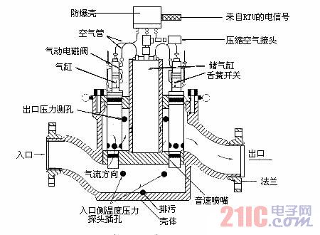
7, CNC switching valve, as shown in Figure 1, the digital valve weighs 1100lb, it has 11 alternative sonic nozzle channels, which are controlled in binary mode. Since the two largest nozzles are divided into maximum channel function and logic control. Binary control gives the CNC valve a resolution of 10bit. The result is an incremental step of the flow rate of 58.7Ac. The RIU's electronic control signal controls the switching of the pneumatic solenoid valve while controlling the pneumatically operated solenoid valve to bring the sonic nozzle into operation. The cylinder is in the middle of the valve and has sufficient energy to rotate the valve twice even if the air supply is interrupted.
There are 4 connecting holes on the CNC valve body: 2 inlets and 2 outlets. The connection port is used to connect the inlet temperature transmitter and the inlet and outlet pressure transmitters. Since the inlet pressure should be very accurate, one inlet should be fitted with two pressure transmitters with a range of 0-75 lb/in2 (table) and 0-200 lb/in2 (table). When the pressure reaches 95% of the first pressure transmitter range, the computer switches the pressure gauge from the first pressure change to the second pressure change. Once a nozzle is opened, gas enters the nozzle from the inlet, flows out of the four nozzles of the housing into the outer casing, and then flows out of the valve body.
Fourth, the basic flow formula
The verification device calculates the mass flow using the following formula
This article refers to the address: http://
![]()
Where: mass flow under M-condition, lb;
P-shell pressure, 1b/in2 (absolute);
A-nozzle throat cross-sectional area, in2; Arkla nozzle diameter range is 0.0620-0.9941in, therefore, its area range is about 0.003-0.776in2;
C-critical flow coefficient, which is a function of specific heat value (equal flow constant). It is a parameter related to the speed of sound of a gas in a gas flow state. In the Arkla system, the representative natural gas estimated critical flow coefficient value is 0.7 (dimensionless). This value is related to pressure and temperature. C is calculated by analyzing the calculated molecular percentage by chromatograph;
Cd-outflow coefficient, or the actual mass flow divided by the theoretical mass flow. In short, it is the efficiency of the nozzle design, which is different for different nozzles and is determined by calibration. Arkla's nozzle outflow coefficient ranges from 0.96 to 1.0 (dimensionless);
R-gas constant, the value is 48.03 divided by the molecular weight of the gas; the molecular weight of the gas to be measured calculated by gas chromatograph analysis is also used for this;
Temperature inside the T-shell, R (°F 460).
The volumetric flow is the mass flow divided by the density, the density is equal to P/ZRT, and the volumetric flow is calculated using the following formula:
![]()
Where: V-volume flow;
The compression factor (RCJohnson, not AGA) in the Z-shell is a value close to 1. The calculated molecular weight and gas composition of the gas chromatograph can be used for this;
The Rv-gas constant is equal to 2.398 divided by the molecular weight of the gas. The molecular weight calculated by the gas chromatograph is also used for this. R and Rv have been adjusted to engineering units.
V. Verification process
The gas flows through the turbine flow meter and then passes through the numerical control valve and sends out four signals, as shown in Figure 2. Two signals for measuring gas pressure and temperature, the other two pulse signals are from the pulse transmitter of the turbine flow meter and the mass flow signal from the digital control valve. It should be noted that the pulse signal of the turbine flowmeter is taken from the lower part of the conversion gear. 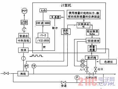
Figure 2 verification system flow chart
When the flowmeter rotates one revolution, the computer measures the data sent by the transmitter on the turbine flowmeter. The first stage gear is the intermediate shifting wheel. For the Rockwell turbine flow meter and American flow meter, their input to output ratio is 122.0555-l. The second stage gear is a shifting gear with an input to output ratio between 1 and 2 to 1.
The flowmeter counter is fixed on the top of the shifting gear. Depending on the gauge diameter, the output of the output shaft is 100 or 1000 Acf per revolution. For a 3-6in flowmeter, the ratio of the counter to the output shaft is 100:1; therefore, the output shaft above the shifting gear represents 1 ft3 per revolution, for a flowmeter of 8 in or larger, the counter and output The ratio between the axes is 1000:1. The flowmeter signal, intermediate gear, shifting gear, and counter give the result of cubic foot flow (Acf) under actual operating conditions.
A pressure, volume, temperature (PVT) chart is installed in the upper part of the counter and used to verify the counter.
The computer inputs the meter temperature and pressure, and calculates the Scfh (standard A3/h) using the Acfh measured by the meter; the mass flow in lb is the density value obtained by the computer from the numerical control valve divided by the standard state. The mass flow rate of the gas flowing through the turbine flow meter and then through the numerical control valve in the system is a constant everywhere.
However, the volumetric flow rate in actual cubic feet varies with the composition, temperature, and pressure of the gas. Therefore, the volumetric flow rate at the valve body is different from the volumetric flow rate at the turbine flow meter. For a certain mass flow, the actual volume flow (Acfh) decreases as the gas density increases. The volumetric flow in the valve body is higher than its flow at the turbine flow meter - this is because the pressure at the valve inlet is lower than the pressure at the turbine flow meter, causing the fluid flow rate to rise slightly. This is why both the pressure and temperature at the valve and flow meter need to be measured.
The difference between the Scfh indicated by the turbine flow meter and the Scfh given by the digitally controlled valve is the error of the turbine flow meter at this flow point. This error is the percent error plotted against the percent flow. This percent gauge error curve is plotted against actual meter flow for a specific gauge constant. The K constant (number of pulses/ft3) can be easily changed by inputting a different gear ratio of the computer.
In order to obtain the smallest error, different sizes of nozzles can be applied through a software program, and the turbine flow meter can be verified by changing the gear ratio. The use of a software program saves time and effort, but instead replaces changing the gear ratio and can repeatedly check the flow until an ideal result is achieved. A detailed chart can be drawn using the results of the verification of 10 different flow points.
Sixth, the conclusion
Arkla's onboard sonic nozzle gas flow calibration system has been used for five years in the verification of turbine flowmeters, and more than 3,500 flowmeters have been verified. The results show that there has never been a gas leak problem, which greatly improves the measurement accuracy.
Ningbo Autrends International Trade Co.,Ltd. , https://www.vapee-cigarettes.com