The actual production of 6N11 and 6AS7 dual-tube amps
Originally, I did n’t like the amplifier. The production of this amplifier was purely accidental. Yesterday I retrieved the gifts of my friends from the post office. I opened the PCB board of the 6N11 and 6AS7 dual-tube amp. The resistors have been soldered on, so I sent a 6AS7. It seems that it is necessary to let me do the amp again. It happened to have the Beijing brand 6N11 produced in 1998 and some 200V electrolysis dismantled from the scrapped computer power supply, so it made up for the remaining components and the hot iron was officially started.
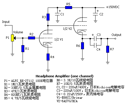
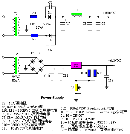
The circuit diagram of the enlarged part of the original machine and the power supply is shown below. The values ​​of all the components have been marked on the circuit diagram. According to the picture, it only took more than 2 hours to solder the circuit board, because there is no suitable at hand. Transformer, I had to connect the secondary windings of a 100W isolation transformer with a 220V output in parallel to get an AC 110V main power supply. In addition, I found a 100W transformer with an output 6.3V winding. First turn on the 6.3V winding of the filament. Seeing that the filaments of the two tubes are slowly lit up, and then connected to the main power supply through the delay circuit, it was observed that there was no abnormality for a while, so I first used a cheap computer headset as the load and connected the sound source, hehe ~~ There was a sound of welding success. 

It should be noted that the power board sent to me by a friend of "Little Boy" is a bridge rectifier RCLC multiple filter circuit, and there is a high-voltage delay connection circuit. Since I did not find a suitable inductance, I simply used the form of RCRC filtering. The power supply of the filament is also different from the original circuit. I used the AC 6.3V direct power supply. In the process of use, I found nothing wrong, the headphones There is almost no noise.
Seeing that the sound can be produced with cheap headphones, I immediately replaced my AKG's K240M, saying that the actual sound quality of this amp can't satisfy me, so I started a long debugging process. Let me report the debugging results to everyone. :
Although the original machine works well, the impression is that the yin is too small, the sound is tight, the sound field is contracted, and the bass control is not good. . . . . In short is not satisfied. Look at the very good design of this circuit, this result should not appear, it seems to be operating on this circuit.
Before commissioning, the parameters of 6N11 and 6AS7 were consulted first. According to previous experience, the adjustment of the operating current of 6N11 at 2-3MA sound quality is satisfactory. The voltage across the measured resistor R3 is nearly 80V, which means that the working current of G1 is 80/47 = 1.7MA. It seems that it is a little small. To increase the working current of G1 can only be the value of reducing the cathode resistance R4. On the board is a 1K resistor that was originally welded by "Little Talents", and another parallel position of the resistor is also reserved for adjustment purposes. Therefore, first adjust the value of R4 to 620 ohms, then measure the voltage across R3, there is a tendency to increase, it seems that the goal has been achieved. However, doing so will make the 6N11's screen voltage too low, and because it is directly coupled, it also affects the operating point of the subsequent 6AS7. Contradictory, through repeated experiments, it was finally determined that R4 = 470 ohms, R3 = 33K, in order to appropriately increase the operating voltage of 6N11, at the same time adjust R5 in the power circuit from the original 4.7K to 2K.
Measured at this time: the voltage across the resistor R3 is 80V, the actual working current of the 6N11 is 2.4MA, the actual listening sense should feel that the sound field is much wider, and the control power of the low frequency has also improved, but the effect is not very large, it seems The problem is mainly in the working current of 6AS7.
By referring to the data of 6AS7, such results are obtained: the maximum power consumption of the single tube is 13W, the maximum operating voltage is 250V, and the current in the class A push-pull circuit is 80MA. Look at our circuit again: the measured cathode voltage of 6AS7 is: 80V, then his current is 80 / R6 = 80 / 3.3K = 24.2ma, which is obviously too small, the method to increase the current of 6AS7 is still to reduce Small cathode resistance, considering the actual working condition of the amp, adjust the value of resistor R6 to 1K, so after adjustment, the actual measurement: 6AS7 cathode voltage is 77V, that is to say the working current of the tube is about 77MA. At this time, the single tube power consumption of 6AS7 is (150-77) V * 77MA = 5.61W, and the maximum power consumption of the tube is not exceeded 13W, but the tube is quite hot at this time, I want to reduce the resistance a little However, it is best not to exceed 100MA, otherwise the tube may enter the nonlinear region.
|


