First, the development background of intelligent power off socket
This article refers to the address: http://
Nowadays, the sockets on the market are basically non-intelligent. When the electrical appliances are connected to the sockets, people generally do not directly cut off the electrical power supply. Therefore, the electrical appliances are always in the standby state. If the outlets are in the on state at this time, the electrical appliances will generate standby. Power consumption, resulting in wasted power. What's more, if there is a short circuit or overload of the appliance, it may cause a fire, and there is a big safety hazard. This runs counter to the concept of energy conservation, environmental protection and safe use of electricity advocated by the society. Therefore, it is very practical to design a safe and energy-saving smart socket. This energy-saving smart socket solution is being established to solve the problem of energy waste and electricity safety to promote low-carbon life.
Second, the principle of design
1, the structure of the system block diagram
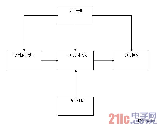
figure 1
As shown in Figure 1, the whole system consists of five parts, namely system power, power detection module, MCU control unit, actuator, and input peripherals.
2, hardware design and principle
System power
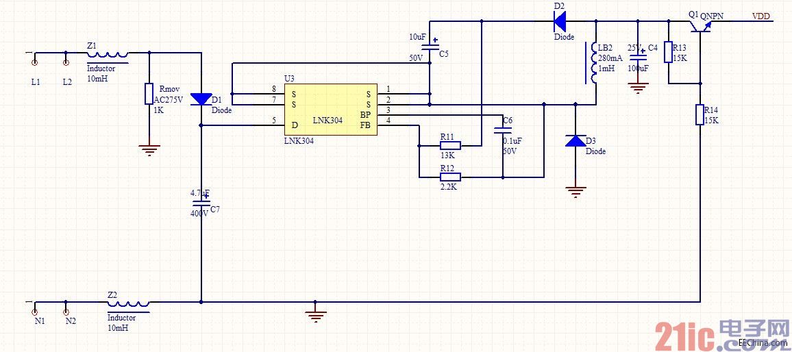
figure 2
The power module is based on the LNK304 design. In Figure 2, L and N are 220V AC interfaces. AC power is applied to the LNK304 chip. The S foot of the LNK304 will output 12V voltage. It will be divided into 6V by R13 and R14 and then enhanced by a triode. The three-stage tube has a part. The voltage drop, so the output voltage VDD is about 5V.
Power detection module
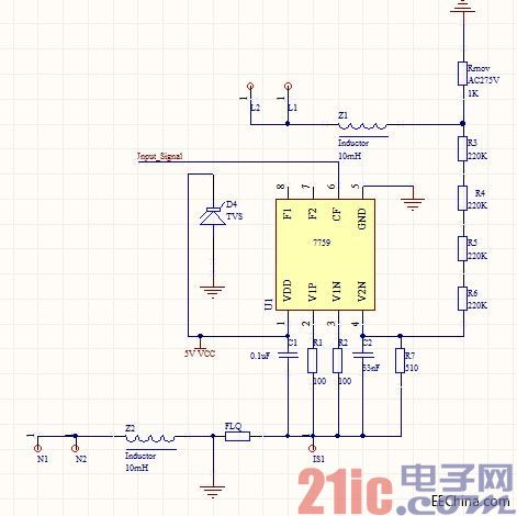
image 3
The power detection uses the FC7759 chip. The FC7759 calculates the power based on the collected voltage signal and the current signal. The CF pin outputs a pulse sequence of a certain frequency according to the power. The frequency of the pulse sequence is proportional to the power. The MCU can judge the power according to the read pulse frequency and issue corresponding commands to control the actuator to perform corresponding actions. In the figure, FLQ is the sampling resistor, the current signal is collected, and the R3, R4, R5, and R6 resistors are divided, and the voltage signal is collected.
MCU control section
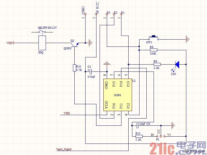
Figure 4
The control part adopts MP20E01 type single-chip microcomputer. This type of single-chip microcomputer has low power consumption, small size and low price, and IO also meets the requirements of this design. As shown in Figure 4, the pulse signal output from the power detection module is sent to the P14 pin of the MP20E01 MCU, the P12 pin reads the button signal, the P15 pin reads the external IR remote control signal, the P13 pin controls the LED indicator, and the P1.1 control relay turns on or off. Disconnect the outlet power.
Executive agency
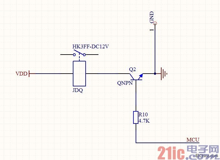
Figure 5
When the MCU detects that the power of the appliance is too high or too low, the control relay is turned on or off to realize the control of the power of the outlet.
Input peripheral
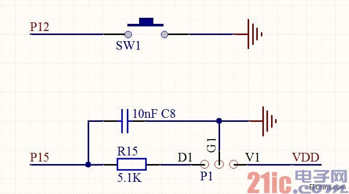
Figure 6
The power of the socket can be turned on and off by the key input, and some function settings (such as setting learning function) can be performed. The infrared remote control is mainly used to turn on the power of the socket.
2, the overall hardware design schematic
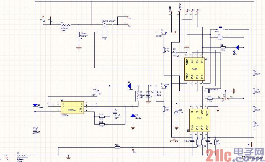
Figure 7
3, program flow chart
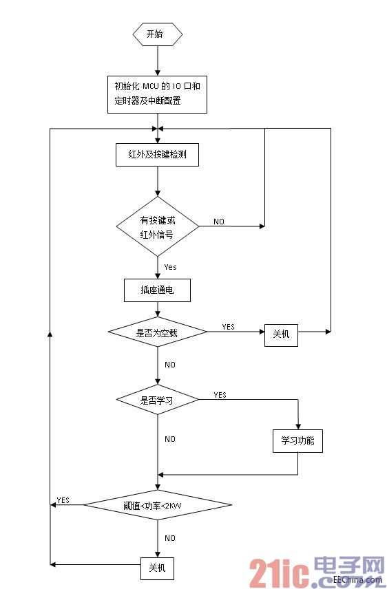
Figure 8
The program flow is shown in Figure 8. After power-on, the microcontroller IO port and timer are initialized, and the initial configuration of the interrupt is performed and then the large loop is entered. Detect button or infrared signal. If there is no signal input, continue to detect button and infrared signal. If there is signal input, turn on the socket power. Then the MCU determines whether it is no-load at this time. If it is no-load, the control relay turns off the power of the socket. If it is not idling, it detects whether the learning function setting flag is 1, and if it is 1, the learning function is set, if not For 1 then go to the next step. The single chip determines whether the current power is within the threshold <power < 2KW range. If it is within the range, it will cycle to the button detection. If the power is not within the range, the relay is turned off after a period of time.
Fourth, summary
This smart socket design This system supports multiple infrared frequency bands, and can operate the system using various infrared remote controllers. It solves the problem of waste of standby energy consumption of electrical appliances, and also solves the safety problem of short circuit or overload operation of electrical appliances, stable operation, strong anti-interference ability, high reliability and humanized operation. More importantly, the structure is simple, the cost is low, and it has a good application prospect.
2.54Mm Box Header,Smt Double Rows 2.54Mm Pitch Mainboard Connector,Box Header Circuit Board Connector,Box Header Mother Board Connections Parts
Dongguan City Yuanyue Electronics Co.Ltd , https://www.yuanyueconnector.com