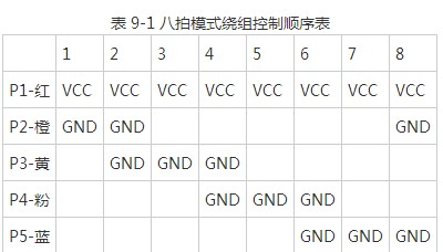
Look again at the appearance and internal structure diagram of the stepper motor above: the stepper motor has a total of 5 leads, of which the red one is the common terminal, which is connected to the 5 V power supply, and the next orange, yellow, pink, and blue correspond to If the A, B, C, and D phases are connected; then if you want to turn on the A-phase winding, you only need to ground the orange wire, and the B-phase is grounded in yellow, and so on; , the following winding control sequence table can be obtained, as shown in Table 9-1:
The part that controls the stepper motor on our board is P1.0~P1.3 multiplexed with the 74HC138 decoder part of the display control on the board. We have already talked about the jumper in Chapter 3. By adjusting the jumper cap The position of P1.0~P1.3 can control the four windings of the stepping motor, as shown in Figure 9-5.
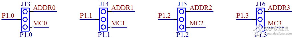
Figure 9-5 shows the selection jumper for decoding and stepping motor
If you want to use the motor, you need to adjust the 4 jumper caps to the left side of the jumper group (the actual position on the development board), that is, the left pin and the middle pin are connected (corresponding to the middle and lower pins in the schematic diagram). ), you can use P1.0 to P1.3 to control the stepper motor. If you want to use the display part again, you need to switch back to the right side. So what if you want the display part to work normally, but also want the motor to work? The jumper cap is kept on the right side, and the control pin of the stepper motor (ie, the pin header on the left) is connected to the IO of other MCUs that are not used for the time being with Dupont wire.
Let's take a look at the schematic diagram of our stepper motor. The control circuit of the stepper motor is shown in Figure 9-6.
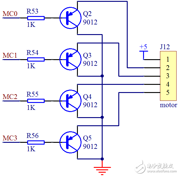
Figure 9-6 Stepper motor control circuit
It is true that the IO port of the microcontroller can directly output voltages of 0 V and 5 V, but the current driving capacity, that is, the load capacity, is very limited, so we add a triode to the control line of each phase to improve the driving capacity. As can be seen from the figure, if phase A is to be turned on, Q2 must be turned on. At this time, phase A, which is the orange line, is equivalent to grounding, so the phase A winding is turned on. At this time, the P1 port of the microcontroller is low by 4 The bit should output 0b1110, which is 0xE; if A and B are the same, then Q2 and Q3 are turned on, and the lower 4 bits of port P1 should output 0b1100, which is 0xC, and so on, we can get the following eight beats Array of IO control codes:
unsignedcharcodeBeatCode[8]={0xE, 0xC, 0xD, 0x9, 0xB, 0x3, 0x7, 0x6};
At this point, it seems that all the logical problems have been solved, and the loop will send the value in this array to the P1 port. However, if you think about it further, you will find that there is still a problem: how often to send data, that is, how long should a beat last? Is it random? Of course not, this time is determined by the starting frequency of the stepper motor. The starting frequency is the highest pulse frequency that the stepper motor can start normally under no-load condition. If the pulse frequency is higher than this value, the motor cannot start normally. Table 9-2 is the stepper motor parameter table provided by the manufacturer, let's take a look.
Table 9-2 28BYJ-48 stepper motor parameter table
Supply voltage Phase number Phase resistance Ω Step angle Reduction ratio Start frequency PPS torque g.cm Noise dB Insulation dielectric strength 5V450±10%5.625/641:64≥550≥300≤35600VAC
The parameters given in the table are ≥550, and the unit is PPS, that is, the number of pulses per second. The meaning here is that the motor can be guaranteed to start normally when you give 550 stepping pulses per second. Then, the duration of a single beat is 1 s/550=1.8 ms. In order to enable the motor to start, we can control the refresh time of the beat to be greater than 1.8 ms. With this parameter, we can write the simplest motor rotation program by hand, as follows:
#includeunsignedcharcodeBeatCode[8]={//IO control code 0xE, 0xC, 0xD, 0x9, 0xB, 0x3, 0x7, 0x6};voiddelay();voidmain(){unsignedchartmp;//Define a temporary Variable unsignedcharindex=0;//Define the beat output index while(1){tmp=P1;//Use tmp to temporarily store the current value of port P1 tmp=tmp&0xF0;//Use & operation to clear the lower 4 bits//Use | operation Write the beat code to the lower 4 bits tmp=tmp|BeatCode[index];//Send the lower 4-bit beat code and the upper 4-bit original value back to P1P1=tmp;index++;//The beat output index is incremented index=index&0x07 ;//Use & operation to achieve 8 return to zero delay();//Delay 2ms, that is, execute one beat in 2ms}}/*software delay function, delay about 2ms*/voiddelay(){unsignedinTI=200;while (i--);}
Compile and download the program to the board and try it! See if the motor is spinning? Remember to change the jumper!
Zysen provides a range of Waveguide Isolator, WR14 to WR650, High power handling,From 1GHz to 40GHz,1dB bandwidth from 0.3% to 15%. Customized frequency and optimized specifications are available. Contact us with your requirement.
Rf Isolator,Waveguide Isolators,Rf Waveguide Isolator,Rf Circulator Isolator
Chengdu Zysen Technology Co., Ltd. , https://www.zysenmw.com