Earlier we talked about the copper paving methods for PCBs with regular shapes and multilateral irregular-shaped PCBs. Today we will talk about how to set the copper paving rules. As the saying goes, there is no rule without rules. If you want to better conduct copper paving, you must first establish copper paving rules.
What kind of rules should be established
To establish rules, we must first clarify which rules we need to pay attention to when laying copper, that is, how we require laying. Below we consider the rules that need to be set for a basic board:
â‘´The connection between the copper sheet and the same network via
⑵The connection method between the copper skin and the same network pad (specifically, it can be divided into SMT and THT to choose different connections)
⑶The connection between the copper sheet and the special package type of the same network (such as BGA)
â‘·The distance between the copper skin and different network vias
⑸The distance between the copper skin and different network pads
⑹The distance between copper skin and different network lines (such as GND, VCC, ANT, differential pair, general network, etc.) is set for copper paving rules
After thinking about the rules to be set, now we start to formally set up our copper paving rules. First find our rule setting function, as shown in Figure 1, click on the menu bar design>>rules
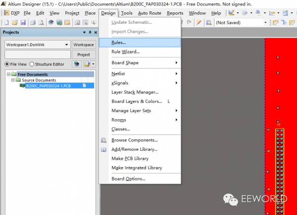
figure 1
At this time, the PCBrules and Constraints Editor dialog box will pop up, as shown in Figure 2:
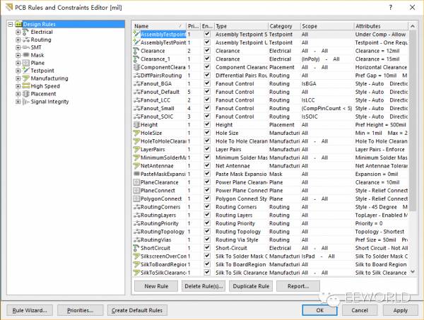
figure 2
From Figure 2 we see a lot of rules, these are the default rules of Altium Designer. Below we first need to find out where the rules for the connection between the copper sheet and the same network are set. See design rules>>plane>>polygon connect style in the left column, as shown in Figure 3. At present, there is a default rule that all the same networks use cross connections.
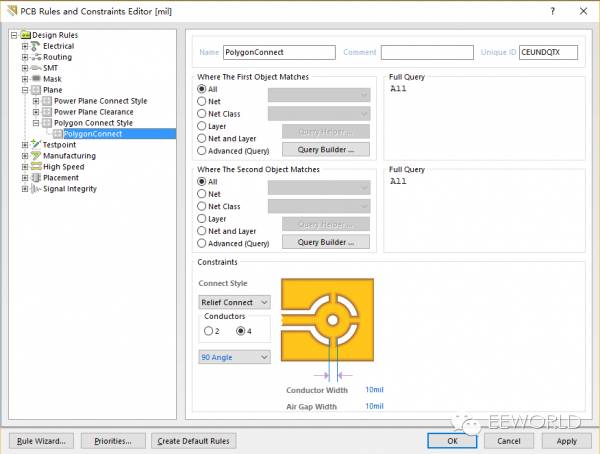
image 3
Recalling the rule requirements we want to set, now we start to create a new rule. As shown in Figure 4, after selecting the PolygonConnect Style option, right-click and select newrule.
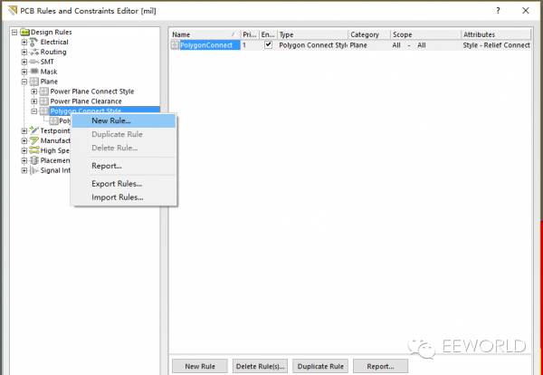
Figure 4
As shown in Figure 5, now we have created a new rule, and then we first give the rule a name "connect tovia", and the naming position is in the red box at the top of Figure 5. (Wrong decision, next time change the color of each box, this time it is so good).
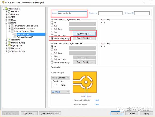
Figure 5
First of all, we are adjusting the connection method of the vias. How do we choose via in the first object selection column? Look at the No. 2 and No. 3 boxes in Figure 5, and select advanced>>queryhelper, then the dialog box shown in Figure 6 will appear:
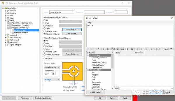
Figure 6
Enter isvia in the top dialog box of the query builder (queryhelper), or find the isvia statement in the column at the bottom left corner, and then click ok. Seeing the PCB rules editor, the first object has selected vias. We now select the connection method, and see the red box in Figure 7, there are three types of connection, here we choose direct connect.
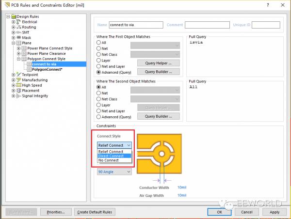
Figure 7
Forgot to choose the second object? It’s too late to choose now~ The same operation method as the first object, but here is ispoly, as shown in Figure 8. Remember to apply, and then our rule is set.
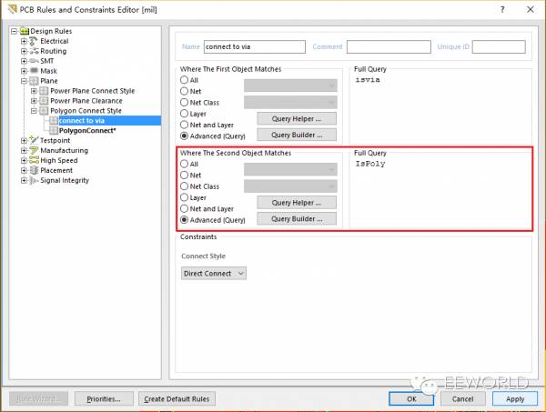
Figure 8
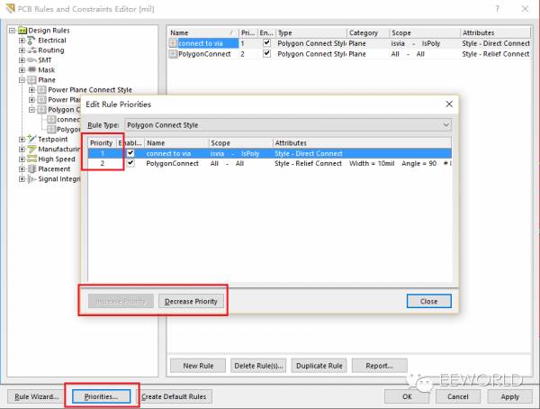
Now there are two rules under polygonconnect style. We found that there is an obvious conflict between the two rules, so let's first introduce how to adjust the priority of the rules. See Figure 9, select the priorities at the bottom, a new dialog box Editor Rules Priorities pops up. In the new dialog box, select the rule you want to adjust. If you want to lower the priority of the rule, select the decrease option, and for the same reason, select the increase option for increasing. From the priority column, we can see the current priority of each rule. The smaller the number representing the priority, the higher the level.
Picture 9
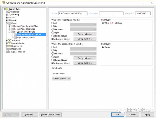
Next, we set the second and third rules. The setting method is the same as the first rule. The pad is ispad and the special package BGA is isbga. This statement is very clear.
Here I also set the BGA connection mode to direct connection, because the connection mode of copper and via is the same as that of BGA, so I merged them into one rule, as shown in Figure 10.
Picture 10
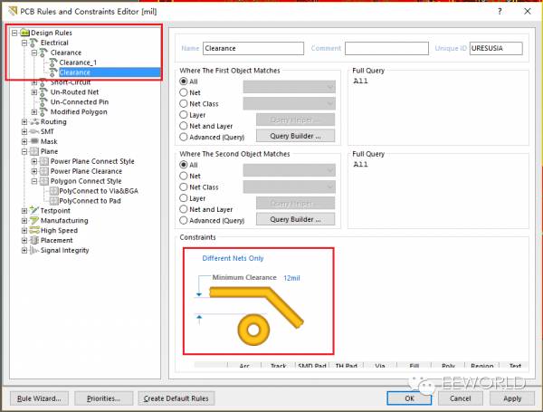
Let's set the interval between the copper sheet and different networks. Also first find the location of the setting, see Figure 11:
Picture 11
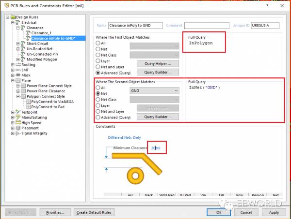
Now let's create a new rule, give it a name, set the next two objects, and then set the spacing. It looks easy to operate.
Picture 12
Does anyone wonder why querybuilder is used? Try it and you will know that, click querybuilder, the buildingquery from board dialog box will pop up, as shown in Figure 12.1:
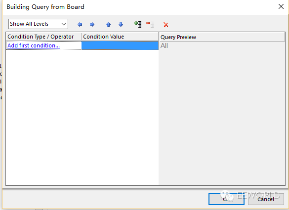
Figure 12.1
You can customize specific commands according to your PCB board, such as selecting iscomponent ('C1'), so you should understand its purpose.
Back to the topic, we now set up a few other rules:
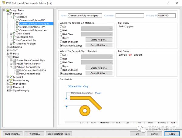
Figure 13
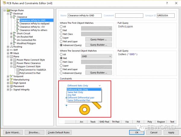
Figure 14
See Figure 14, we can choose whether the spacing setting is between different networks, between all networks, or the same network. Of course, we chose the defense nets only here.
Looking at the very simple rule settings, I didn't want it and it took a while. Do I have to set it up every time I draw a board? I have a little mood for being lazy.
Look at Figure 15, select design rules and right-click, do you see export rules? By the way, export here, select export, as shown in Figure 16, confirm the rules you want to export, and then click ok to save your file (Figure 17). The export was successful. Next time when you draw the board again, import your rules. Where to import it? You should have caught it when exporting just now. Oh, besides, you can also export a single or single-type rule.
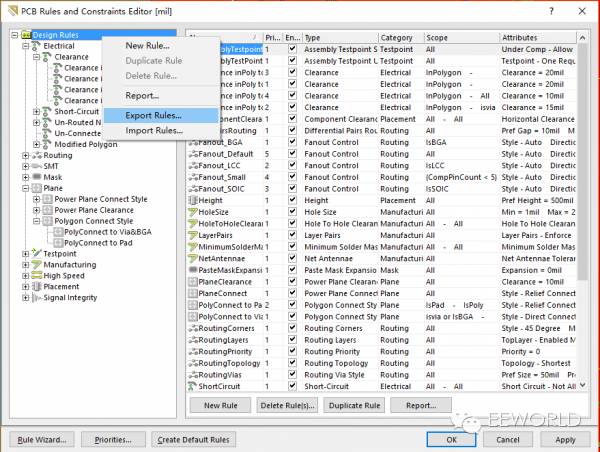
Figure 15
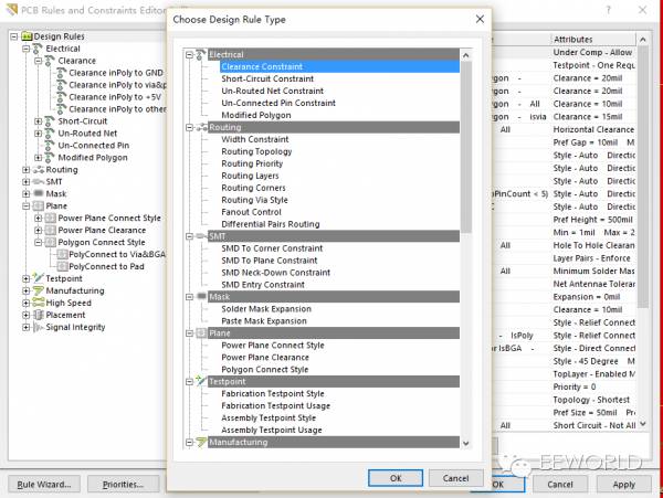
Figure 16
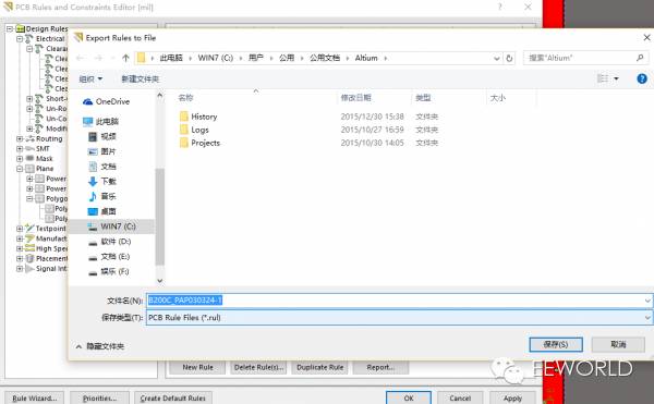
Figure 17
Here we basically set up our rules, remember to adjust the priority at the end. Then we can carry out our copper paving below.
Power Meter is a monitoring and testing instrument which determines the power consumption of a connected appliance and the cost of the electricity consumed.
Built-in 3.6V rechargeable Batteries ( . The purpose of the batteries is to store the total electricity and memory setting
Resetting
If an abnormal display appears or the buttons produce no response, the instrument must be reset. To do this,
press the RESET button.
Display Mode
Entire LCD can be displayed for about 1 minute and then it automatically gets into Model. To transfer from
one mode to the other, press the FUNCTION button.
Mode 1: Time/Watt/Cost Display Display duration(how long) this device connect to power source.LCD on first line shows 0:00 with first two figures mean minutes(2 figures will occur while occur at 10 min) and the rest shows seconds. After 60mins, it displays 0:00 again with first two numbers meas hour(2 figures will occur at 10hours)and the rest shows minutes. The rest can be done in the same manner which means after 24 hours, it will re-caculate. LCD on second line displays current power which ranges in 0.0W 〜 9999W. LCD on third line displays the current electricity costs which ranges in O.Ocost 〜 9999cost. It will keep on O.OOcost before setting rate without other figures.
Mode 2: Time/Cumulative electrical quantity Display Display duration(how long) this device connect to power source.
LCD on first line shows 0:00 with first two figures mean minutes(2 figures will occur while occur at 10 min) and the rest shows seconds. After 60mins, it displays 0:00 again with first two numbers meas hour(2 figures will occur at 10hours)and the rest shows minutes. The rest can be done in the same manner which
means after 24 hours, it will re-caculate. LCD on second line displays current cumulative electrical quantity which ranges in 0.000KWH 〜 9999KWH without other figures. LCD on third line displays"DAY"- "1 'Will be showed on numerical part(the other three figures will be showed at carry) which means it has cumulated electrical quantity for 24hours(one day). The rest can be done in the same manner untill the maximal cumulative time of 9999 days.
Mode 3: TimeA^bltage/Frequency Display LCD on first line displays the same as Mode 1 dones. LCD on second line displays current voltage supply (v) which ranges in 0.0V 〜 9999V .LCD on third line displays current frequency (HZ) which ranges in 0.0HZ 〜 9999Hz without other figures.
Mode 4: Time/Current/Power Factor Display LCD on first line displays the same as Mode 1 dones.LCD on second line displays load current which ranges in 0.0000A 〜 9999A. LCD on third line displays current power factor which ranges in 0.00PF 〜 LOOPF without other figures.
Mode 5:Time/Minimum Power Display LCD on first line displays the same as Mode 1 dones. LCD on
second line displays the minimum power which ranges in 0.0W 〜 9999W. LCD on third line displays character of "Lo" without other figures.
Mode 6: Time/Maximal Power Display LCD on first line displays the same as Mode 1 dones. LCD on second line displays the maximal power which ranges in 0.0W 〜 9999W. LCD on third line displays character of "Hi" without other figures.
Mode 7: Time/Price Display LCD on first line displays the same as Mode 1 dones. LCD on third line displays the cost which ranges in O.OOCOST/KWH 〜 99.99COST/KWH without other figures.
Overload Display: When the power socket connects the load over 3680W, LCD on second line displays the''OVERLOAD[ with booming noise to warn the users, (selectable choice)
Supplemental informations:
1: Except [OVERLOAD[ interface, LCD on first line display time in repitition within 24hours.
2: LCD on first line, second line or third line described in this intruction take section according to two black lines on LCD screen. Here it added for clarified purpose.
3. Mode 7 will directly occur while press down button "cost".
4. [UP"&"Down" are in no function under un-setting mode.
Setting Mode
1. Electricity price setting
After keeping COST button pressed lasting more than 3 seconds(LCD on third line display system defaults price, eg O.OOCOST/KWH ),the rendered content begins moving up and down which means that the device
has entered the setting mode. After that, press FUNCTION for swithing , then press "UP"and "DOWN" button again to set value which ranges in OO.OOCOST/KWH 〜 99.99COST/KWH. After setting all above, press COST to return to Mode7 or it will automatically return to Mode7 without any pressing after setting with data storage.
Power meter socket, Energy meter socket, Energy meter cost socket, Power meter cost socket, Energy power meter socket
NINGBO COWELL ELECTRONICS & TECHNOLOGY CO., LTD , https://www.cowellsocket.com