This paper introduces a SAR antenna stability platform test module based on PXI bus technology. The test module is the main subsystem of the automatic test system of the SAR antenna platform, and mainly performs functions such as decoding and outputting of the simulation turntable position signal, platform tracking error signal acquisition, and signal analysis processing.
Introduction to PXI bus technologyPXI bus technology is a new open, modular instrument bus specification released by NI, which is an extension of the PCI bus in the field of instruments. It develops the PCI bus technology defined by the CompactPCI specification into mechanical, electrical, and software specifications suitable for applications in test, measurement, and data acquisition applications. The PXI bus has exactly the same performance as the benchtop PCI specification and is based on the addition of proven specifications and requirements to the PCI bus core technology. It meets the requirements of test and measurement users by adding trigger buses and reference clocks for multi-board synchronization, star-trigger buses for precise timing, and local buses for high-speed communication between adjacent modules. The PXI specification adds environmental testing and active cooling requirements to the CompactPCI mechanical specification to ensure interoperability and system integration of multi-vendor products. It defines Microsoft Windows NT and Windows 95 as its standard software framework, and requires all instrument modules to have Win32 device drivers written in accordance with the VISA specification, making PXI a system-level specification that ensures easy integration and use of the system. , thereby further reducing the development costs of end users.
Test module structureAs a PXI bus test card based on Windows platform, the instrument module includes two parts: PXI card and host driver software. The PXI card is responsible for the processing of the test data, and the host driver is responsible for the communication.
PXI card structureThe PXI card is divided into three parts: the incremental encoder decoding module, the RS-232 interface module, the DSP main processor and the PXI bus interface. The structure of the test card is shown in Figure 1. The incremental encoder decoding module cooperates with the 422 differential receiver for decoding the two-axis position data of the antenna simulation turntable; the DSP main processor completes the processing of the test data, and the PXI interface module mainly completes the conversion interface of the PCI bus signal to the local bus. The RS-232 interface module accepts the serial output signal of the PSD (photosensitive position detector), which is used in the test system to detect the error of the tracking simulation turret movement of the antenna platform.
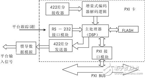
Figure 1 Structure of the PXI card
PSD serial output signal readingThe test system uses PSD processing circuit to send one frame of data every 5ms through the standard asynchronous serial port, and uses TI TMS320VC5510 as the main processor to meet the requirements of data storage space (up to 176KB RAM inside), but it only has McBSP for synchronous communication. It is not possible to directly implement asynchronous serial communication, and it is necessary to cooperate with the DMA channel of the DSP to implement asynchronous communication through software. Each byte sent by the PSD is taken as one frame of data, and the falling edge of the start bit is used as the frame synchronization signal. By oversampling, each bit (including the start bit) is used as a 16-bit Word, and the stop bit is only Take 8 bit WORD. A byte is buffered to the fixed buffer through the DMA channel. When one frame of data (10 WORDs) is completely acquired, the DMA interrupt is sent to notify the DSP for processing. For the phenomenon of boot misplacement garbled which is common in serial communication, the judgment of the special bit is discarded.
Incremental encoder decoding module designThe test module needs to receive the position information of the platform from the antenna platform test simulation turntable. In various motion control systems, the incremental photoelectric encoder is often used as the feedback detection component, and the output is A and B two-phase signals with a difference of 90 degrees. And the periodic pulse reset signal Z, the positive and negative phase difference between the two phase signals A and B determines the forward and reverse directions of the motion, the pulse output count of the A and B two-phase signals determines the magnitude of the position motion, and Z is the zero-crossing reset pulse. The whole decoding logic design is shown in Figure 2. Since the position information of the simulation turntable used in the test system has two directions of orientation and roll, two sets of decoders are needed to decode the position information in two directions.
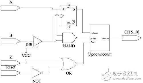
Figure 2 decoding logic design
Main processor workflowDSP is a key component of the test card, and is responsible for tasks such as data processing, storage, simulation of inertial data generation, and communication with the host computer. The DSP uses the PSD to send data as the time reference. After receiving the data sent by the PSD every 5ms and storing it, the first step is to read the counter value from the incremental encoder decoding module through the EMIF (Extern Memory Interface). After being converted into two 16-bit angular quantities, the proportional operation is stored and sent to the external inertial data analog module through the EMIF interface, and the self-aligning machine signal converted into the inertial output is sent to the stable platform. In order to ensure continuous recording of data, the data is stored in the DSP's DARAM (Dual-Access RAM, dual-port RAM), and uses ping-pong storage (ie, there are two storage areas, when one of the storage areas is full, through the PXI bus up) The bit machine issues an interrupt and then begins writing data to another memory area). We set up each storage area to store 1000 sets of data (each set includes 4 positions of electronically controlled turntable orientation, roll attitude, and tracking error of the platform in these two directions), so each storage area includes 4000 Words.
PXI bus interface hardware designKNM1L Series Moulded Case Circuit Breaker
KNM1L series Moulded Case Circuit Breaker is MCCB , How to select good Molded Case Circuit Breaker suppliers? Korlen electric is your first choice. All moulded Case Circuit Breakers pass the CE.CB.SEMKO.SIRIM etc. Certificates.
Moulded Case Circuit Breaker /MCCB can be used to distribute electric power and protect power equipment against overload and short-current, and can change the circuit and start motor infrequently. The application of Moulded Case Circuit Breaker /MCCB is industrial.
Korlen electric also provide Miniature Circuit Breaker /MCB. Residual Current Circuit Breaker /RCCB. RCBO. Led light and so on .
KNM1L series Molded Case Circuit Breaker,KNM1L series Small Size Molded Case Circuit Breaker,KNM1L series Electrical Molded Case Circuit Breaker,KNM1L series Automatic Molded Case Circuit Breaker
Wenzhou Korlen Electric Appliances Co., Ltd. , https://www.zjmoldedcasecircuitbreaker.com