Abstract: As a mainstream chip for 32-bit RISC microprocessors, ARM chips have been developed and widely used. As a result, the test requirements of the ARM chip are more robust, while the test workload is increasing and the test complexity is increasing. This paper presents an ARM Cortex-M3-based microprocessor test method that can also be used for microprocessor-like testing of similar structures.
0 Preface
With the development of semiconductor technology, the integrated circuit process technology has evolved from deep sub-micron to nano-scale, and the increase in transistor integration has increased the complexity of the chip, and the function of a single chip has become stronger. Founded in Cambridge, England in the 1990s, ARM was primarily licensed to sell chip design technology. Microprocessors using ARM technology intellectual property (IP cores), ARM microprocessors, are used throughout the industry. Consumer electronics products. Communication Systems. Network Systems. In various product markets such as wireless systems, microprocessor applications based on ARM technology account for more than 70% of the market share of 32-bit RISC microprocessors. The widespread application and development of ARM chips also pose challenges for testing, IC testing. Functional testing at actual speed is generally used, but the development of semiconductor technology has led to the growth of test development engineering resources according to geometric laws. The performance of automatic test equipment (ATE) cannot keep up with the increasing development of device I/O speed, and it is also difficult to meet. The high-resolution requirements of timing signals used in microprocessor testing such as ARM have required continuous improvement in the performance of automated test equipment, resulting in rising test costs. In addition, because the complexity of the ARM chip is getting higher and higher, in order to test its function, the workload of manually writing test vectors is extremely huge. In fact, the manual writing workload of an ARM chip test vector may reach dozens of people. even more. In this paper, an efficient test vector generation method is proposed for the working principle of ARM Cortex core, and the ARMCortex-M3 core microprocessor is tested on the BC3192 test system.
1 microprocessor test method
The integrated circuit test mainly includes functional test and DC parameter test. The test of the microprocessor also includes two functions of function and DC parameter test. Microprocessors contain a rich set of instructions, and there are many types of microprocessors. It is difficult to have uniform test specifications between different microprocessors. In order to make the test universal, it is necessary to establish a unified model for the testing of the microprocessor, as shown in Figure 1. The chip test system provides power and clock for the microprocessor under test, and can simulate the microprocessor's analog communication interface to control the microprocessor's operation, and simultaneously apply the excitation vector with the simulation timing to achieve the test purpose.
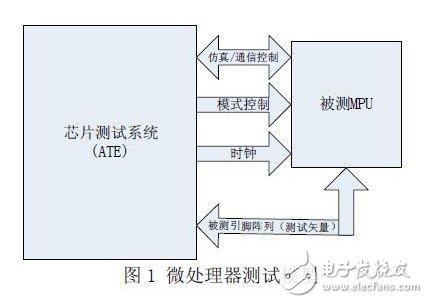
There are two types of microprocessor-based analog communication interfaces, one is a microprocessor with an emulation interface (such as JTAG), and the other is a microprocessor without an emulation interface. For a microprocessor equipped with a JTAG-like interface, the tester Perform functional or parametric tests on the DUT by emulating a JTAG interface. There is no chip equipped with an emulation debug interface, and the test model can be selected according to the external interface and boot mode of the chip.
1.1 Tracking debug mode
Most microprocessors provide a trace debug interface, such as the most commonly used JTAG interface. In addition to JTAG debug, the Cortex-M3 core also provides a dedicated instruction tracking unit (ITM). JTAG (Joint Test AcTIon Group, federation) The Test Action Group is an international standard test protocol (IEEE 1149.1 compliant) that is primarily used for on-chip testing. Most advanced devices now support JTAG protocols such as ARM.DSP.FPGA devices. The standard JTAG interface is 4 lines:
TMS.TCK.TDI.TDO, respectively, mode selection. clock. Data input and data output lines. JTAG was originally used to test the chip, so testing the microprocessor using the JTAG interface has many advantages.
The JTAG interface is used to simulate the microprocessor. The test system simulates a JTAG interface to simulate the microprocessor. The core of the simulation is the state machine simulation. Figure 2 shows the JTAG TAP used by the test system. State transition diagram of the controller.

JTAG communication control can be achieved by a tester to simulate state transitions.
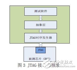
JTAG has a uniform specification at the physical layer and the data link layer, but may differ slightly for different chip emulation test protocols. To make the test model generic, we have an abstraction layer on the JTAG interface of the test model, as shown in Figure 3. The abstraction layer in the figure converts a variety of control functions into data streams that the chip can recognize to control the working state of the chip under test.
1.2 Boot Mode / FLASH Programming Mode
For microprocessors that do not have an emulation debug interface, the boot function can be used to test the microprocessor. The simulation test cannot be implemented because there is no emulation debugging function. Therefore, for this type of microprocessor test, the test code needs to be loaded in the chip. Most microprocessor chips have a power-on boot function that can be used to load test code into the microprocessor for boot function and DC parameter testing. For a microprocessor equipped with FLASH, the test code can be downloaded to the on-chip FLASH to test the function and parameters of the microprocessor.
In order to achieve test control of the microprocessor, in general, the test system utilizes the on-chip communication interface of the microprocessor to communicate with the on-chip test program to perform functions and parameter tests in cooperation with each other.
2 ARM Cortex-M3 test
2.1 Introduction to the ARM Cortex-M3 Core
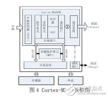
The ARM Cortex-M family of microprocessors is primarily used in low cost and low power applications such as smart metering. Human interface device. Automotive and industrial control systems. Large household appliances. In the areas of consumer products and medical devices. Figure 4 shows a simplified block diagram of the Cortex-M family of microprocessors.
The ARM Cortex-M3 core is equipped with several debug-related features.
The main thing is program execution control, including downtime (halTIng). Stepping. Instruction breakpoint. Data observation point. Register and memory access. Performance profiling and various tracing mechanisms. The Cortex-M3 debug system is based on ARM's latest CoreSight architecture. Although the kernel itself no longer contains a JTAG interface, it provides a debug access interface (DAP) bus interface. The DAP can access the chip's registers, access system memory, and be accessed while the core is running, which provides interface support for chip testing. Microprocessors integrated with the Cortex-M3 core typically provide a debug port (DP) connected to the DAP. Currently available debug ports include SWJ-DP, which supports both traditional JTAG debug and new serial line debug protocols. Cortex- The M3 core can also mount an embedded trace macro unit (ETM). The ETM can continuously send trace information, which is sent to the outside of the kernel through the trace port interface unit (TPIU), and ARM for external integration and tracking information analyzers. The chip can capture the executed instruction information of the TIPU output and send it to the chip test system.
2.2 Test Vector Generation
Testing an ARM chip with an automatic test equipment (ATE) is a traditional test technique that has the flexibility to program test vectors and focus on application-related functional blocks and parameters. However, due to the complexity of the functions and applications of the ARM chip, the capabilities of the test system are also required. This requires the test equipment itself to have the ability to test a variety of different functional modules, including the logic. simulation. RAM. Test capability of high speed or high frequency circuits, etc. At the same time, the test system preferably has its own independent test capability for each test channel, avoiding the use of resource sharing, so that it can be flexibly applied to various test functions. So conventional ARM chip test equipment often requires a fairly high configuration to cope with test needs.
The meaning of the test is very broad. For ARM chip testing, multiple types of tests can be defined. Different types of tests need to generate different types of test vectors. The test vector generation method can be manually compiled, but most of them need to be generated by the test vector generation tool (ATPG) to produce a relatively complete test set. The ARM chip test method described in this article generates test code by means of the corresponding ARM chip development tool, and then generates a test vector by a dedicated test vector generation tool. The advantage of this approach is that it can generate test vectors for test sets that are of interest to ARM chip application developers, so it is more efficient and the test cost can be controlled at a lower level. In addition, you can transcode with a large number of ARM chip applications, which can greatly reduce the workload. The disadvantage is that it is not easy to use algorithms to automate the generation of complete test code.
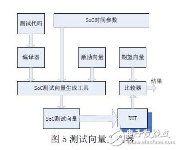
Figure 5 shows the ARM chip test vector generator. The test code can generally be obtained from the ARM chip development routine. The test vector is compiled into ARM chip executable code by the compiler, and then mixed with the excitation vector and the expectation vector to generate a complete ARM chip test vector. ARM chip test vector generation tool passing time Parameters to determine the test code. The timing relationship between the excitation vector and the expected vector, ARM chip time parameters can be obtained from the chip manual. After the test vector is generated, it is downloaded to the test system graphics card through the BC3192 integrated development environment, and the test program is started. The excitation vector is sequentially applied to the input port of the ARM chip under test, and the output is monitored and compared to obtain the test result. In summary, the generation of test vectors is the core of ARM chip testing. The test vector generator described in this paper generates test logic by inputting ARM chip executable code and chip time parameters, which is easy to use. Efficient features are now being tested in multiple ARMCortex core microprocessors.
3 Conclusion
By analyzing the working principle and tracking debugging method of ARM Cortex-M3 core, this paper combines the common ARM integrated development environment and the test vector generator of BC3192V50 test system to quickly and efficiently generate microprocessor test vector based on ARM Cortex-M3 core. To complete the function and DC parameter test. The method described in this case is also suitable for testing by other microprocessors.
Substation Structures,Telegraph Pole,Substation Steel,Substation Steel Structures
JIANGSU HONGGUANG STEEL POLE CO., LTD. , https://www1.hgsteelpole.com