Dielectric constant measurement technology is widely used in various fields such as civil, industrial and military. This paper mainly discusses the common methods of dielectric constant measurement. Firstly, the national standards were compared and summarized. Then the basic principles, application scope, advantages and disadvantages and development status of several commonly used measurement methods were discussed respectively. Finally, several measurement methods were compared and summarized, and the conclusions were drawn.
1 IntroductionDielectric constant is an important physical property of an object. It has important theoretical and practical significance for the study of dielectric constant. In dielectric engineering, electromagnetic compatibility, biomedical, microwave, electronic, food processing, and geological exploration in electrical engineering, the electromagnetic properties of matter are used, and the measurement of dielectric constant is required. At present, the application of the dielectric constant measurement method can be said to be in various fields of civil, industrial and national defense.
In the food processing industry, dielectric constant measurement techniques are widely used in storage, processing, sterilization, grading, and quality inspection. For example, by measuring the dielectric constant, some indicators of fresh fruit and vegetable quality, water content, fermentation and drying process are indirectly reflected. In addition, process parameters such as sterilization time and power density are determined according to the dielectric constant and water content of the food. It is also one of the important applications [1].
In the subgrade compaction quality inspection and evaluation, if the conventional method is used, although the measurement result is relatively accurate, the workload is large, the cycle is long, the speed is slow, and the road surface is damaged. Since the water content, temperature and density of the soil will have different effects on its dielectric properties, the entire area can be tested by radar to calculate the value of the dielectric constant, and the density of the subgrade can be obtained by analyzing the dielectric properties. The parameters such as compaction degree achieve the purpose of quickly measuring the density and compaction of the roadbed [2]. In addition, the complex permittivity measurement technique has also been applied in the monitoring of soil and water pollution [3]. Earthquakes can also be predicted by measuring the dielectric constant of rocks [4].
The above is a partial application of dielectric constant measurement in civil applications, and it has important applications in industry. Typical examples are the application of low dielectric constant materials in very large scale integrated circuit processes and the application of high dielectric constant materials in semiconductor memory devices. In the integrated circuit process, as the transistor density increases and the line width decreases, the parasitic effects of capacitance and resistance in the interconnect increase, and the traditional insulating material silicon dioxide is replaced by a low dielectric constant material. of. Currently, Black Diamond of Applied Materials, as a low dielectric constant material, has been applied to the commercial production of integrated circuits [5]. In the semiconductor memory device, the high dielectric constant material can solve the problem of the thickness limit of the gate oxide layer caused by the size reduction of the semiconductor device, and has special physical characteristics, and can realize a new device with special performance [6]. In the military, dielectric constant measurement technology is also widely used in the manufacture and testing of radar and various special materials.
The application of dielectric constant measurement techniques can be said to be numerous. The measurement technique of dielectric constant has been widely used in various fields of civil, industrial and national defense, and there is room for development and necessity. We summarize the methods for measuring the dielectric constant, and can more clearly understand the current state of measurement methods, and provide a method that may be suitable for some applications. It has certain theoretical and engineering application significance.
2. Overview of dielectric constant measurement methodsThe measurement of dielectric constant can be divided into solid, liquid, gas and powder (particle) measurement according to material classification [7]. Solid dielectrics are the most widely used in measurement and can be generally classified into solids of fixed shape and size and solids of uncertain shape. There are fewer methods for testing liquids and gases relative to solids. For liquids, the dielectric constant can be measured by the waveguide reflection method with an error of about 5% [8]. In addition, the method of measuring the liquid loss tangent and dielectric constant at 90 °C and power frequency is given in the national standard [9]. For gases, the specific test method is small and the accuracy is not very high. A measurement method is given in [10]. Based on the measurement of the resonance frequency, the oscillation is generated in the LC series resonant circuit. The digital frequency meter is used to measure the resonance frequency, the pressure is continuously changed, and the resonance frequency at the current pressure is recorded. The data is processed by a graph or a linear regression method to obtain a capacitance change rate to calculate a relative dielectric constant.
Table 1 is a national standard method for measuring the dielectric constant of solids (excluding the method of abolition) and its requirements for frequency, range of dielectric constant, materials, and the like.
Table 1. National Standard Methods for Measuring Solid Dielectric Constants [9, 11-25]
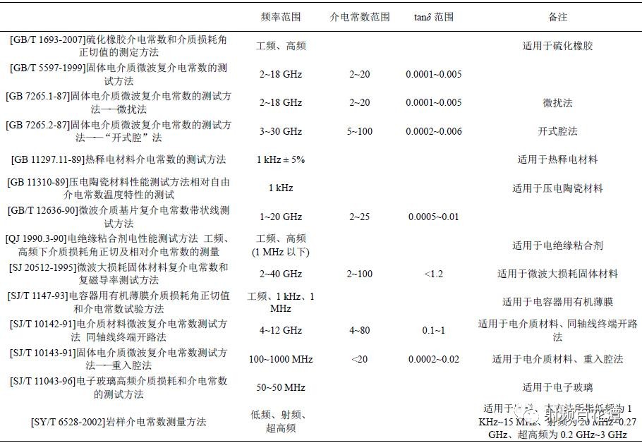
As shown in Table 1, the process of the perturbation method and the open cavity method has been described in detail in the national standard, but the range of the applicable frequency and the dielectric constant is limited. Therefore, in the case of different materials and different frequencies, the national standard also gives the corresponding specific measurement method. It can be seen that the method analyzed above is not applicable at will. In the case of different systems, different materials, and different required frequencies, specific analysis of specific problems is required to arrive at the most accurate method. The national standard measurement method covers frequencies below 50 MHz and 100 MHz to 30 GHz, which can be said to be a wide frequency coverage, but different materials and environments are applicable to different ranges. The dielectric constant covers a range of 2 to 100, and the measurement of the dielectric constant and the higher dielectric constant close to 1 is scarce, and the loss is generally on the order of 10-3 to 10-4.
3. Several main methods for measuring dielectric constantGenerally speaking, the current methods for measuring the dielectric constant mainly include a concentrated circuit method, a transmission line method, a resonance method, a free space wave method, and the like. Among them, the transmission line method, the concentrated circuit method, the resonance method, etc. are laboratory measurement methods, and the measurement is usually performed in a laboratory, and a corresponding sample collection technique is required. In addition, the dielectric constant after foaming of known dielectric constant materials is usually obtained by empirical formula [26]. In the following, the principles, characteristics and development status of these methods are separately explained.
3.1. Centralized circuit method
The concentrating circuit method is a method of filling a capacitor with a consumable material in a low frequency band, and using a capacitance parameter and a measured admittance to introduce a dielectric constant. The principle formula is:

(1) where Y is admittance, A is the capacitance area, d is the distance between the plates, ε0 is the dielectric constant of air, and ω is the angular frequency.
In order to measure the admittance, the Q value (quality factor) and frequency are usually measured by a parallel resonant circuit, and the dielectric constant is derived. Since its maximum frequency is limited by the minimum inductance, the highest frequency of this method is typically 100 MHz. The minimum inductance is typically around 10 nHz. If the inductance is too small, the high-frequency stray capacitance affects too much. If the frequency is too high, a standing wave is formed, and the resonant frequency is changed while the radiation loss suddenly increases. However, this method is not suitable for low-loss materials. Because the Q value measured by this method is only about 200, the tan δ measured by the network analyzer is only about 10-4. This method is not only less accurate, but can only measure lower frequencies, and has been infrequently applied under the requirements of existing communication applications.
3.2. Transmission line method
The transmission line method is a type of network method that places the medium into the test system at the appropriate location as a single-port or dual-port network. In the case of dual port, the electromagnetic parameters of the microwave are obtained by measuring the s parameters of the network. Figure 1 is a schematic diagram of the principle of the dual port transmission line method.
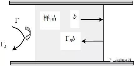
Figure 1. Schematic diagram of the dual port transmission line method
The transmission coefficient is expressed by Γs, which is
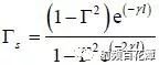
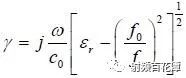
(2) wherein Γ represents the reflection coefficient of the air sample, γ is the propagation coefficient, and l is the sample length. The reflection coefficient can be expressed as

Where f0 is the cutoff frequency of the transmission line when there is no sample, and f0=0 for the TEM mode transmission line. γ is expressed as
Can be found:
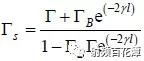
Where ΓB is the reflection coefficient.
Simultaneously measure the phase and amplitude of the transmission coefficient or reflection coefficient, change the sample length or measurement frequency, and measure the amplitude response at this time. The simultaneous equations can determine the relative dielectric constant.
In the case of a single port, the complex permittivity of the material is obtained by measuring the complex reflection coefficient Γ. Therefore, common methods include a filled sample transfer line segment method, a sample-filled coaxial line termination method, and a method of placing a sample at an open transmission line terminal [27]. The first method measures the amplitude response by changing the length of the sample and measuring the frequency to find εr. This method can measure the change of the minimum point of the transmitted wave and the reflected wave with the length and frequency of the sample, and can avoid the iterative solution of the complex transcendental equation. However, this method is limited to low and medium loss media, and for high loss media, there is no multiple reflection in the sample. The transmission line method is suitable for solids and liquids with large εr, but not for gases with small εr.
As early as 2002, the transmission reflection method was used to achieve stable measurement of complex permittivity at any frequency for samples of any thickness. The advantages of the NRW T/R method (ie transmission line method based on transmission/reflection parameters) are simple, high precision and suitable for waveguide and coaxial systems. However, this method is not stable when the sample thickness is an integral multiple of the half-wavelength wavelength corresponding to the measurement frequency. At the same time, there are multi-value problems in this method. It is usually a waste of time and inconvenient to select samples with different frequencies or different thicknesses for measurement. In addition, high precision measurements are not possible for very thin materials [28]. The earliest application of the reflection method to measure the dielectric constant was Decreton and Gardial. In 1974, the dielectric constant of the sample to be tested was derived by measuring the reflection coefficient of the open waveguide system. The coaxial reflection method is the generalization and deepening of the reflection method, that is, the sample to be tested is equivalent to a two-port network, and the scattering coefficient of the network is measured by a network analyzer, and the dielectric constant of the material is tested accordingly. The results show that the coaxial reflection method has certain feasibility in measuring the dielectric constant of high loss materials. It can measure and calculate the dielectric constant of most high loss dielectrics. For the cavity method, the dielectric constant of high loss materials cannot be measured. Very large supplementary application value [29].
In 2006, a scalar method for measuring the dielectric constant of low-loss thin film materials was proposed. The method uses the transmission line method to measure the principle, firstly measures the loss of the dielectric to be measured, indirectly obtains the reflection coefficient, and then derives the dielectric constant of the medium from the relationship between the reflection coefficient and the dielectric constant. The film can be divided into three categories: low loss, high loss and high reflection. It is proved by experiments that the loss of the three films changes substantially with the same frequency, and the high frequency is slightly different, and the allowable error range can be approximated. This method is practical, but it is not suitable for measuring the surface roughness of the medium [30]. In recent years, a new method for determining the permeability of the complex dielectric constant of a Ka-band millimeter wave loss material has been proposed and a scattering equation for determining the complex permittivity and permeability of the sample is given. This method has the following advantages: 1) Computational complex permittivity and permeability equations are decoupled, do not require iteration; 2) The frequency range to be measured is relatively wide; 3) The dielectric constant is eliminated compared to the conventional method Measure the dependence on the length of the sample and the position of the reference surface; 4) Eliminate the uncertainty of the NRW method at certain frequencies [31]. Others have extended the electromagnetic spectrum of the ellipsometry method from visible light to infrared light to the millimeter wave band. The ellipsometry method calculates the photoelectric and geometric parameters by measuring the change of the sample reflected wave or the projected wave relative to the polarization state of the incident wave. The imaginary part of the complex permittivity obtained by the millimeter wave ellipsometry is lower than the real part, that is, the calculated imaginary part has a certain error, but it provides an important reference for the further study of the ellipsometry [32].
3.3. Resonance method
The resonance method is a method of measuring the dielectric constant as a part of a resonant structure, and is divided into a perturbation method, a method of completely filling a resonator space, and a method of partially filling a resonator space. All padding can be calculated using equation (6)
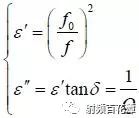
Where ε' is the real part of the complex permittivity, ε'' is the imaginary part of the complex permittivity, Q is the figure of merit, tan δ is the loss tangent, and f0 is the resonant frequency without the sample.
Partial filling is mainly to reduce the sample size and the influence of the material on the resonator parameters, which is difficult to calculate accurately and is generally used for correction.
The perturbation method requires a relatively small size and the relative frequency offset is less than 0.001. In this case, the specific size shape can be expressed by the fill factor s:
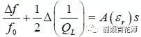
Where f0 is the resonant frequency without sample, QL is the quality factor, εr is the relative dielectric constant, and A(εr) is a function of the relative dielectric constant and the perturbation cavity parameters.
At this time, regardless of the shape size, the relative dielectric constant can be easily obtained by obtaining the filling factor s. With this method, the dielectric constant of almost all materials can be measured, but the same shape is required for calibration. In terms of frequency, when the frequency is higher than 1 GHz, the dielectric constant can be measured by the waveguide cavity, but when the frequency is higher than 10 GHz, the measurement of the dielectric constant is proposed because the fundamental cavity is too small. challenge. There are many specific methods of resonance method, such as rectangular cavity method, cavity perturbation method, microstrip line resonator method, strip line resonator method, dielectric resonator method, high Q cavity method and so on. In recent years, new methods have emerged and improved for the resonance method.
The cylindrical cavity measurement dielectric constant method is a method for measuring the dielectric constant introduced in China in 1987. After the research and development of the test fixture and the study of the slit cavity, the test results are more accurate. Its frequency test range is approximately 1~10 GHz [33]. In addition, improvements to the open cavity approach are also very comprehensive and mature. In the open cavity method, the method of forming the cut-off cavity by the cylindrical medium in two large flat metal plates is widely used, and the measurement of the relative dielectric constant εr is relatively accurate, but the measurement error of the loss angle tanβ is relatively large. In 2006, it was proposed to measure the dielectric constant of the waveguide dielectric cavity, which can simultaneously measure the microwave loss and dielectric constant, but can only be used to measure samples with a relative dielectric constant greater than 10 [34]. At the same time, because the parallel plate open cavity method will have a part of energy along the structure between the feed line and the upper and lower metal plates to form radiation loss, it has been proposed to increase the short circuit plate between the upper and lower metal plates on the feed side to prevent radiation loss, and The system was designed and manufactured to test cylindrical media through a single port [35]. In the past two years, there have been many improvements and developments in open cavities. The open-cavity automatic measuring system, which is co-operated by 38 universities and Southeast University, is not only easy to operate, but also has a relative dielectric constant and loss tangent uncertainty of less than 0.17% and 20.4%. In addition, it has been proposed that the application of quasi-optical cavity method in millimeter wave and submillimeter wave has high Q value, easy to use, no damage to the film, high sensitivity, easy sample placement, and ability to detect the uniformity of complex dielectric constant of large-area medium. Advantages, but still can only be measured at several separate frequency points [36].
In summary, the resonance method can basically measure the dielectric constant of materials in all frequency ranges, but most of the researches on the millimeter wave range in the existing methods; good single-mode performance, high Q value, simple cavity preparation and sample preparation, and easy operation; The measurement accuracy is high; but the measurement of the loss tangent has not been very accurate, and generally can only be measured at several separate frequency points; and because the resonant frequency and inherent quality can be measured accurately, it is very suitable for low loss media. Measurement of materials. The technique of the resonance method has been perfected, but there are still some shortcomings: how to ensure that the cavity length accuracy of the single-frequency point method is ignored for a long time; the transcendental equation for extracting the relative dielectric constant has a multi-value solution; there are still many error sources, etc. [37].
3.4. Free Space Law
The free space method can also be regarded as the transmission line method. Its principle can refer to the line transmission method, by measuring the transmission and reflection coefficients, changing the sample data and frequency to obtain the value of the dielectric constant. Figure 2 is a schematic view of the same.
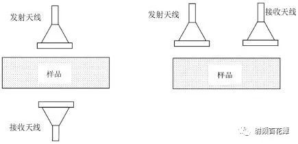
Figure 2. Schematic diagram of the free space method
The free space method is different from the transmission line method. The transmission line method requires the waveguide wall to be in full contact with the material being tested, and the free space method overcomes this disadvantage [38]. The free space method preserves the advantage that the line transmission method can measure a wide frequency range. The free space method requires that the material have sufficient loss, otherwise standing waves will form in the material and cause errors. Therefore, this method is only suitable for high frequency situations above 3 GHz. Its maximum frequency can reach 100 GHz.
3.5. Six-port measurement technology
In addition, there is another method for six-port measurement technology. Its measurement system is shown in Figure 3.
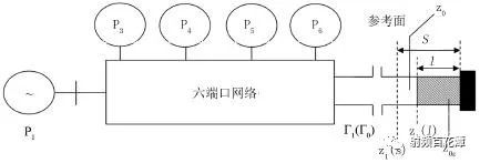
Figure 3. Six-port measurement system
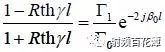
When the dielectric sample is not filled, the waveguide loss is ignored, the short-circuit segment reflection coefficient Γl0 = -1, and the reference surface reflection coefficient is

Where β0 is the propagation constant in the air waveguide.
Fill the medium close to the board and measure the reflection coefficient Γ1.
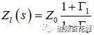
Known by transmission line theory
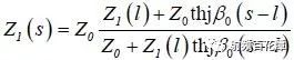
The characteristic impedance of the sample-filled waveguide is represented by Zoε, and γ is its complex propagation constant, and the sample is short-circuited by the terminal.

Obtain the s parameter from (8)-(11)
among them  In the waveguide for the main mode TE10,
 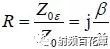 , brought in by finishing
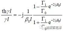
Where γ=α+jβ, α is the attenuation constant of the dielectric-filled waveguide, β is the phase constant of the dielectric-filled waveguide, and the above equation (13) is obtained to obtain α and β, which are substituted into the following formula.
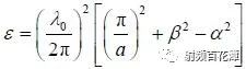
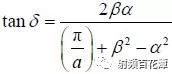
That is, the relative dielectric constant ε and the dielectric loss tangent tan β are obtained. Where λ0 is the wavelength of free space and a is the width of the waveguide [39].
The six-port technology is a microwave automatic measurement technology developed in the 1970s, which has the advantages of low cost and simple structure. Currently, six-port technology is widely used in security protection, microwave metrology and industrial online measurement. The six-port technique is a method of measuring the scalar instead of the measurement vector, replacing the measurement of the amplitude with the measurement of the amplitude [40]. Therefore, its requirements for equipment accuracy and complexity have declined. At the same time, the six-port technology shows great advantages in the realization of the connection with the computer control interface, which is beneficial to the automatic measurement of microwave impedance and network parameters.
As early as the 1990s, China's academic circles proposed many verification methods, and designed a high-precision automatic measurement system, and proposed the selection of microwave probes for measuring low-loss media [41, 42]. The six-port technology is still evolving and improving in recent years. The academic community has proposed many new ways to solve the transcendence equation. At the same time, Matlab is used to solve the transcendence equation, and Labview is used as the man-machine interface, and Matlab is embedded in it [43]. All in all, the six-port network can measure over a wide frequency range. Currently, the six-port system of NIsT Lab can measure the frequency range from 10 MHz to 100 GHz; the six-port network has higher accuracy, and the measurement of s-parameters can be achieved. The frequency of manual measurement; compared with the automatic network analyzer, the structure is simple, the cost is low, and the volume is small; the measurement and optimization can be performed by the computer and its software, which is more conducive to automation.
3.6. Summary of measurement methods
The applicable occasions, advantages and disadvantages of the above methods can be simply summarized into Table 2.
Table 2. Summary of methods for measuring dielectric constant

The measurement technique of dielectric constant has been applied to all aspects of production and life, and the measurement standards are also very clear. The range of frequencies that can be measured in national standards already covers below 50 MHz and 100 M to 30 GHz. However, it has a clear definition of the type of test material and the range of values ​​of dielectric constant and loss angle, so that the range in which various standards can be applied is not very extensive. As far as measurement methods are concerned, several major measurement methods have their own advantages and disadvantages. The concentrating circuit method is suitable for low frequency conditions; the transmission line method has a wide frequency coverage and is suitable for materials with large dielectric constant. Most of the methods are not suitable for high loss and thin film materials, and the method is simple and accurate; the resonance method can only be limited. Measurement at frequency point, suitable for low-loss materials, simple and accurate method, good single mode; free space method is relatively poor, but can achieve on-the-spot measurement; high-precision six-port network method, low cost of six-port network, frequency Wide coverage, more suitable for a variety of measurement needs in the future, but there is no specific standard for reference. It can be seen that there is no way to completely replace other methods. Different methods have their own advantages and disadvantages. It is very necessary to choose a specific method in different situations.
5. ConclusionNowadays, the measurement technique of dielectric constant is now progressing and improving. The summary of its measurement method is to hope that readers have a clearer and systematic understanding of it and can meet the possible future development trend. Of course, different engineering requirements and experimental environments must have specific measurement methods. It is believed that with the development of the electronic technology and communication industry, there will be more and better methods for measuring the dielectric constant, making a greater contribution to our daily life, industrial development and military progress.
Resolver is a kind of commonly used angle detection component, because of its simple structure, reliable operation, and its accuracy can meet the general detection requirements

Resolver,Encoder Troubleshooting Resolver,Custom Resolver,Online Resolver
Yuheng Optics Co., Ltd.(Changchun) , https://www.yuhengcoder.com