This paper uses fingerprint recognition technology to design a simulated car fingerprint recognition door lock. According to the special situation of the car, the actuator is designed and the corresponding hardware is selected. On the basis of the Biokey SDK algorithm, the secondary development is carried out to improve the function of the software. Set up a simulated car fingerprint identification door lock system to test whether the action of the actuator meets the requirements.
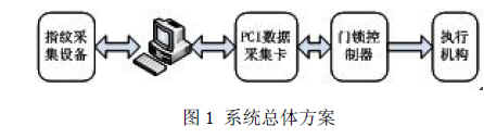
1 system overall design system can be divided into three parts: automatic fingerprint identification system consisting of fingerprint acquisition equipment and computer, control system composed of computer and control components, door lock controller and bidirectional DC motor to simulate car door lock (such as figure 1).
1.1 Fingerprint collection instrument fingerprint collection is the first step in the automatic fingerprint identification system. Fingerprint collectors are usually classified according to the image acquisition method. The commonly used fingerprint image capture methods are as follows: optical device image acquisition; crystal sensor image acquisition; ultrasonic device image acquisition. Among them, ultrasonic scanning is considered to be a very good type of fingerprint imaging technology [1]. The author compares various fingerprint collectors on the market and selects the U.are.U4000 fingerprint collector with the best price. It features automatic reading of fingerprint images, digital fingerprint images transmitted to the computer via USB interface, and support. Central Control Technology Biokey SDK development tools, etc. [2].
1.2 Data Acquisition Card This system uses the PCI9111DG data acquisition card produced by Taiwan ADLink Company to realize the data input and output function. The acquisition card has three data ports for communication with the outside world: CN1, CN2, CN3. This system only uses CN3 port. ACLD-9137 is the terminal block with CN3. The author uses the analog output channel (port 30) and analog ground port (port 9) on the terminal block and the corresponding signal input on the door lock controller. The ports are connected to achieve control of the actuator.
1.3 car door lock
This article refers to the address: http://
The car door lock is composed of a door lock controller and an actuator. This system adopts the bidirectional DC motor of Alto central control door lock as the actuator, and simulates the switching action of the door lock by controlling the positive and negative rotation of the motor.
The function of the door lock controller is to control the switch of the door lock actuator and shorten the working time to save energy [3]. The system uses a door lock controller consisting of a relay and a 555 monostable trigger to control the actuator. The circuit diagram of the door lock controller is shown in Figure 2. 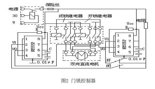
The working principle of the door lock controller: the door lock open and close button keeps the state, the controller does not output the execution signal to the actuator; press the unlock button, the actuator rotates forward, when the button is pressed for the duration T>TP (555 monostable) When the trigger output drives the relay rectangular pulse signal width), the actuator working time is equal to TP; the latching process is the same as the unlocking process; when the unlocking and latching switches are pressed at the same time, due to the interlock function between the relays, the door lock is now The controller does not output a signal to the actuator to protect the circuit.
Pulse width calculation formula:
TP= RC ln 3 =1.1RC
In the formula, R and C are the external resistance of the 555 monostable trigger and the size of the capacitor [4].
2 software design
2.1 Biokey SDK algorithm description
The Bioeky SDK algorithm is a fast and accurate 1:1 and 1:N fingerprinting algorithm that is open to software developers and system integrators. When using the Biokey SDK for fingerprint recognition (identifying 2000 to 6000 fingerprints), it is not necessary to pre-classify the fingerprint by name, PIN, etc., and it can be easily completed in 1 to 5 seconds [5]. The standard flow of the fingerprint identification algorithm is shown in Figure 3: 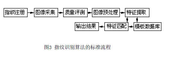
2.2 Software interface functions and implementation of the Biokey algorithm for secondary development. Fingerprint registration is implemented by the function OnOnEnrollZkfpengx2(). During the registration process, the fingerprint of everyone is stored in the computer memory according to the process number. Image saving is achieved by the function: OnMeuSaveb and the function OnMeusavej. The save path can be set according to the actual situation. The two recognition forms 1:1 and 1:N are implemented by: OnMeuOnetoone() and OnMeuOneton(). After the matching is successful, the signal is output by the function m_PCI9111.WriteDOPort(). The variable temp in the function indicates the voltage of the output signal. The author sets temp=6, that is, the output voltage is set to 6V.
The flow chart of the fingerprint identification system is shown in Figure 4. 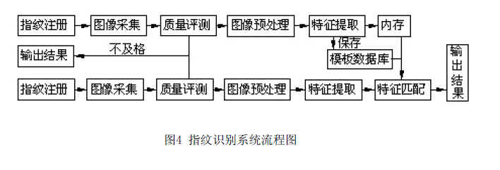
3 System test preparation: First, connect the pin jumper JP1 on PCI9111DG to U1 (the range of output signals is required to be 0V~10V). Then launch the software, register 5 different fingers and save the image, exit the software and re-enter. Then connect the power to the door lock controller, select the 1:N recognition type on the software interface, and compare the test system with different fingers. Use the multimeter voltage file to measure the voltage signals of the 30 and 9 terminals on the line terminal ACLD-9137, and observe the action of the bidirectional DC motor at the same time. Hold with 0, 1 for unlocking, and -1 for blocking. System test results are shown in Table 1: 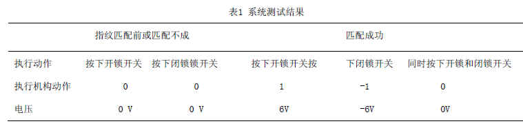
4 Conclusions This system uses optical fingerprint acquisition instrument to collect fingerprint images, and uses computer to perform fingerprint image calculation. The simple and practical door lock controller is designed to effectively control the door lock actuator, which reduces the cost of the system. The test results show that the car fingerprint recognition door lock scheme designed in this paper is feasible. It can effectively and conveniently control the opening and closing of the door lock. The fingerprint recognition system makes the door lock have sufficient security.
The author of this paper innovates: This paper proposes to apply fingerprint recognition technology to the car door lock to solve the problem of insufficient safety and reliability of the traditional car door lock. It lays the foundation for the application of fingerprint recognition technology in car anti-theft system.
references
[1] Zhao Liang, Gong Mingmin. Research on Identity Authentication Technology Based on Fingerprint Identification[J].Control of Microcomputer,2006,9-1:301-304
[2] Central control URU4000B fingerprint collector. http://
[3] Liu Xigong. Central control door lock system [M]. Domestic car central control / remote control door lock and anti-theft system troubleshooting manual. Beijing: Mechanical Industry Press, 2008: 2-3
[4] Qin Zenghuang. Trigger and Sequential Logic Circuits [M]. Electrotechnical. Beijing: Higher Education Press, 2008:321-322
[5] Guan Haixin. Member Management System Based on Fingerprint Identification [D]. [Master's Thesis], Sichuan: Sichuan University, 2006
[6] Guo Chuanjun. Research on Computer Fingerprint Technology[J]. China Science and Technology Information, 2007(5): 108-109
Live Pro Speaker,8 Woofer Speaker,8 Inch Woofer Speaker,Woofer Speaker 8 Inch
Guangzhou Yuehang Audio Technology Co., Ltd , https://www.yhspeakers.com